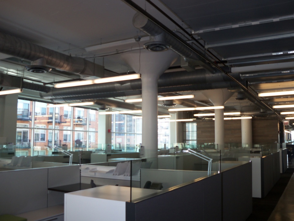
When Sara Lee Corp. changed its name to Hillshire Brands and relocated from the suburbs to downtown Chicago in December 2012, the company gained a new lease on life.
Hillshire moved a portion of its corporate headquarters into the newly renovated, four-story 400 South Jefferson Street building in the city’s West Loop. Built in 1944 for the Newman-Rudolph Lithographing Co., the 230,000-sf structure was stripped down to its cast-in-place concrete frame and rebuilt with a modern glass curtain wall façade, new passenger elevators, major building system updates, and an indoor parking garage.
The $70 million, fast-track project—led by Proteus Group (architect, core and shell), Leopardo (general contractor, core and shell), Perkins+Will (architect, interior build-out), Clune (general contractor, interior build-out), Sterling Bay Cos. (owner/developer), Environmental Systems Design (MEP/FP), Project Management Advisors (project management), and Colliers (tenant representative)—was completed in just 10 months using a BIM/VDC/IPD workflow.
The core and shell team had the full 10 months to complete its portion of the project, but the interior build-out team had just four months. The interior work entailed four general office floors, three test kitchens, and a tower housing conference rooms.
Initially, the base building contractor modeled the as-built conditions using BIM, after which the interior design was added by Perkins+Will, before releasing the model to Environmental Systems Design. ESD had just four weeks to complete bid and permit documentation for the building’s MEP and fire protection systems.
5 Tips for collaborating with BIM
1. All consultants working in BIM should coordinate during architectural model development, rather than after completion of the architectural model. Communicating your expectations prevents coordination issues from occurring later in the project design. In the case of the Hillshire HQ project, the architects and engineers met before the BIM model was initiated to talk about past concerns and project design expectations.2. Set up trade drawing sheets at the start of the project. Designers often forget to set up trade drawing sheets and don’t think about them until the end of the project when they want to print. The absence of trade drawing sheets can hold up a project. As cool as the 3D model is, the 2D drawing is what everyone will use after the design has been completed.3. BIM programs are not CAD; don’t use them as if they were. Most AEC professionals learn how to design in 2D CAD, so when moving into BIM they try to replicate what is done in CAD, like drawing text boxes, without utilizing the “smarts” in BIM. In addition, understand that you’re working in a 3D environment and you need to pay attention to the “Z” axis, or the vertical plane. For the first time, height needs to be defined. How high are you mounting the ductwork or the light fixture? Those questions need to be answered early on.4. Use BIM to create ventilation schedules. Take advantage of the information already held in the model, such as the defined volume and ceiling height of each room. Let the BIM model fill out ventilation schedules and calculate air quantities of individual air terminals.5. Set up electrical equipment properties and panel schedules at the beginning. This speeds up circuiting in the end. Every time a piece of equipment is placed into the BIM model, fill in the information about the piece of equipment from the start so that schedules auto-populate at the end.— Amanda Carter
Could BIM really speed up design, eliminate coordination issues among the trades, and limit requests for information during construction? ESD set out to find the answer.
Beginning with Autodesk’s Revit MEP, ESD engineers created a 3D interactive model. Using Revit’s automatic scheduling feature, they simulated the building’s potential loads, including air quantities and electrical loads. Defining the space types and square footage of each room within the model allowed BIM to automatically calculate the ventilation requirements of the applicable mechanical codes for each space. These quantities were scheduled and allowed the mechanical engineers to assure that the proper amount of supply air would be provided to each room.
Similarly, by defining specific loads and demand factors for the electrical elements within the Revit model, the panel schedules were able to self-populate and properly calculate both the total connected and demand load for each piece of electrical equipment in the building. This allowed for proper sizing of over-current protection for each piece of equipment throughout the electrical distribution, as well as the associated feeders and conduit.
Because each of the schedules was based on the definition of elements within the model, they were able to self-populate and automatically update to changes, allowing for fewer coordination issues within the construction documents. The model also helped the team lay out the ductwork so that it coordinated with light fixture locations in the building’s open ceiling layout, and ensured that the design of the electrical equipment met the dimensions of the designated equipment areas.
Together, these elements produced a complete model of the building’s MEP infrastructure with much more certainty than the traditional 2D modeling, and did so within the tight time frame.
Unfortunately, however, BIM can’t read the human mind. When the base building contractor altered the layout of the large electrical rooms in the field, the project’s contractor couldn’t build out the space as designed by ESD, per the base building model. Switches and equipment were housed in different locations within the space, resulting in an RFI that required re-coordination.
After the contractor in the field proposed a couple of options for the final equipment layout and ESD submitted the redesign, the large electrical rooms were built within the desired time frame. Despite this challenge, using BIM to coordinate between trades on the front end still resulted in fewer RFIs and allowed the Building Team to meet the tight design and construction schedule, avoiding major discrepancies in the field.
Comparing 2D to 3D for Performance
As a comparison, ESD previously designed a similar project in 2D CAD. This second project employed the same lead engineers and interiors contractors, with similar square footage and a large commercial kitchen, and was designed and constructed as the base building was being completed. The result? The Hillshire headquarters had approximately half the RFIs of the 2D-designed project.
To further test the success of BIM in the field, ESD selected a few locations throughout the Hillshire headquarters where “snapshots” of the Revit model were compared to post-construction photos of the same space. In every case, side-by-side visual comparisons showed that the construction documents were almost identical to what was installed in the field. Considering the speed at which both design and construction were completed, it was amazing that the end result so closely matched the original design.
While BIM was used on the project primarily to coordinate between trades during design, in the end, it helped the entire Building Team meet a tight schedule, eliminate coordination problems between the trades, and limit RFIs in the field.
Amanda Carter, FE, is an Electrical Engineer and Associate at Environmental Systems Design, Chicago (www.esdesign.com). She can be reached at acarter@esdglobal.com.
Related Stories
| Aug 11, 2010
Polshek Partnership unveils design for University of North Texas business building
New York-based architect Polshek Partnership today unveiled its design scheme for the $70 million Business Leadership Building at the University of North Texas in Denton. Designed to provide UNT’s 5,400-plus business majors the highest level of academic instruction and professional training, the 180,000-sf facility will include an open atrium, an internet café, and numerous study and tutoring rooms—all designed to help develop a spirit of collaboration and team-oriented focus.
| Aug 11, 2010
University of Florida aiming for nation’s first LEED Platinum parking garage
If all goes as planned, the University of Florida’s new $20 million Southwest Parking Garage Complex in Gainesville will soon become the first parking facility in the country to earn LEED Platinum status. Designed by the Boca Raton office of PGAL to meet criteria for the highest LEED certification category, the garage complex includes a six-level, 313,000-sf parking garage (927 spaces) and an attached, 10,000-sf, two-story transportation and parking services office building.
| Aug 11, 2010
GSA celebrates 60th anniversary
The U.S. General Services Administration today is commemorating its 60th anniversary as it engages in one of its its most challenging assignments ever—helping to achieve the goals of the American Recovery and Reinvestment Act.
| Aug 11, 2010
Draft NIST report on Cowboys practice facility collapse released for public comment
A fabric-covered, steel frame practice facility owned by the National Football League’s Dallas Cowboys collapsed under wind loads significantly less than those required under applicable design standards, according to a report released today for public comment by the Commerce Department's National Institute of Standards and Technology (NIST).
| Aug 11, 2010
Callison, MulvannyG2 among nation's largest retail design firms, according to BD+C's Giants 300 report
A ranking of the Top 75 Retail Design Firms based on Building Design+Construction's 2009 Giants 300 survey. For more Giants 300 rankings, visit http://www.BDCnetwork.com/Giants
| Aug 11, 2010
USGBC honors Brad Pitt's Make It Right New Orleans as the ‘largest and greenest single-family community in the world’
U.S. Green Building Council President, CEO and Founding Chair Rick Fedrizzi today declared that the neighborhood being built by Make It Right New Orleans, the post-Katrina housing initiative launched by actor Brad Pitt, is the “largest and greenest community of single-family homes in the world” at the annual Clinton Global Initiative meeting in New York.
| Aug 11, 2010
AIA report estimates up to 270,000 construction industry jobs could be created if the American Clean Energy Security Act is passed
With the encouragement of Senate majority leader Harry Reid (D-NV), the American Institute of Architects (AIA) conducted a study to determine how many jobs in the design and construction industry could be created if the American Clean Energy Security Act (H.R. 2454; also known as the Waxman-Markey Bill) is enacted.


