


Constructing contemporary building enclosures while avoiding installation problems during construction and performance problems in service is an unrelenting challenge for Building Teams. The margin for error is minimal. Increasingly complex building designs, thin profit margins, and demanding schedules do not allow for rework during construction, nevermind callbacks and disputes after occupancy.
In the mechanical/electrical/plumbing (MEP) realm, a well-established practice for managing these challenges during the preconstruction phase is the “coordination drawings” process. In stark contrast, building enclosure preconstruction coordination (or lack thereof) is typically characterized by shop drawings focused on each enclosure component separately, with a generic representation of the adjacent construction.
Although most of this article discusses the general and trade contractors’ efforts during the preconstruction/construction phase, a fair discussion on shop drawings is incomplete without emphasizing the importance of the design documentation.
The designer of record must clearly articulate the basis of design for the building enclosure systems in the contract documents. By avoiding illustrating complicated details, or by omitting or illegibly illustrating the intent for air, water, vapor (as appropriate for the project conditions), and thermal barrier continuity, the designer of record handicaps the project’s chances for success.
Adjacent systems/substrates omitted
It is common for construction teams to submit enclosure shop drawings comprised solely of manufacturer’s standard product details without substrate identification and information on interfacing components. This practice is at best inefficient, requiring revisions and avoidable extra administrative time by the Building Team.
It is even more common that the installation proceeds on this basis without regard to project-specific conditions. Interface details are field-coordinated under the pressure of the construction schedule, and, when conflicts are identified, the solutions available to the Building Team are often limited, as products are already fabricated and installed.
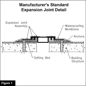
Case Study: A multiunit residential project in Maryland included a building expansion joint within the plaza waterproofing system, including several horizontal-to-vertical transitions. The initial expansion joint submittal consisted of a manufacturer’s standard detail (Figure 1). The illustration did not show the geometry at the corner transitions or any of the interfacing materials. The construction team produced four iterations of shop drawing revisions, spanning several months, to arrive at the final version suitable for executing the work in the field.
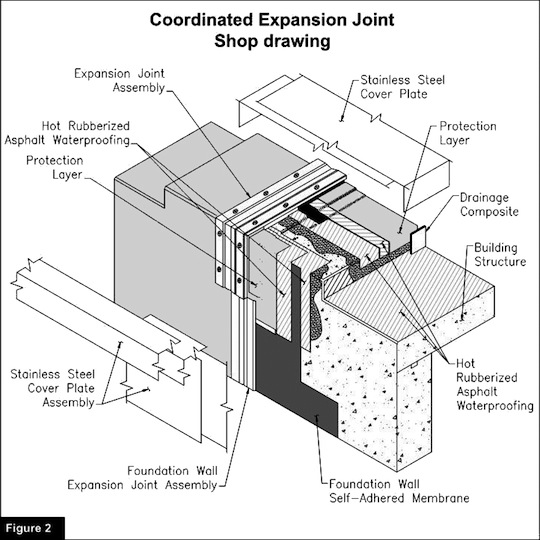
The Building Team certainly would rather have used the time spent generating and reviewing these revisions for other important tasks. How could they have collectively made better use of time? The design drawings should have highlighted the need for the expansion joint to traverse an outside corner. The construction team should have made an effort to anticipate the interfacing materials, establish a plan to execute the work on paper in advance of the construction, and include the necessary information in the initial version of the shop drawings; producing something similar to Figure 2.
Often, meetings among the affected contractors, manufacturers, and design team members can facilitate a critical review of the substrates and interfacing materials that must come together at these challenging details.
Adjacent Systems “By Others”
When building enclosure shop drawings do show adjacent enclosure components, they rarely do so accurately and are often adorned with the construction industry’s perilous “by others,” and installers are left to deal with the fallout resulting from the lack of coordination at interfaces between enclosure components.
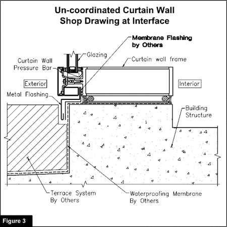
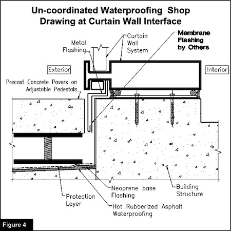
Case Study: A high-rise building in Virginia included a glazed curtain wall adjacent to a terrace with hot-applied rubberized asphalt (HRA) waterproofing. The membrane flashing integration between the HRA base flashing and curtain wall sill was well illustrated in the contract documents.
Both the waterproofing contractor and glazing contractor prepared their own (otherwise satisfactory) shop drawing packages, and each included a version of this transition detail from their own perspectives (Figures 3 and 4). Both parties noted the membrane flashing integration as “by others.” Fortunately, the general and trade contractors identified this near miss shortly before installing terrace overburden that would have concealed the transition.
Near misses like this are not welcome on construction projects and tend to cause lost time and added effort by many parties. How could this situation have been avoided through a preconstruction coordination process? Similar to a MEP coordination drawings session, the affected contractors, manufacturers, and design team members could have met, overlaid the two versions of the transition detail, and asked “Who owns the membrane transition flashing?” and, subsequently, “Have we verified compatibility of all adjacent materials?” This exercise would have quickly facilitated the production of a coordinated, construction-ready shop drawing transition detail.
Conclusion
The building enclosure as a whole is no longer a combination of individual materials, but a holistic system with overall performance requirements that rely on the integration and coordination of building components to establish system continuity. Building enclosure shop drawings play a critical role in guarding against common performance, cost, and schedule pitfalls associated with the transitions between adjacent enclosure components. Building Teams can follow some basic guidelines to derive value from coordinated building enclosure shop drawings:
- Owners: Consider investing in Building Enclosure Commissioning (BECx) at a project's inception. BECx is a quality-assurance-focused process designed to verify that the Building Team is meeting the Owner’s project requirements. A BECx Agent is well positioned to help the Building Team manage the coordination challenges discussed above.
- Designers: Prepare design documents with clear designation for how the air, water, vapor (as appropriate for the project conditions), and thermal barriers transition between adjacent enclosure components to provide continuous building systems.
- Designers: Include a requirement for coordinated building enclosure shop drawings in the project specifications. Require singular, fully superimposed details (with regards to compatibility, performance, and constructability/sequencing) at each enclosure transition.
- Contractors: Submit building enclosure shop drawings that include substrate information, adjacent materials, flashings, sealants, and sequencing requirements that are coordinated between the affected trades and ready for execution in the field.
- Contractors: Understand that coordination of building enclosure systems is a critical aspect of improving building performance, managing risk, improving trade coordination and scheduling, and increasing trade contractor production.
About the Authors: John N. Karras and Jeffrey D. Kerr are with Simpson Gumpertz & Heger Inc.’s (SGH) Building Technology division in Washington, D.C. Both have diverse construction industry experience in construction management and building enclosure design, consulting, and investigation.
Related Stories

| Dec 20, 2011
BCA’s Best Practices in New Construction available online
This publicly available document is applicable to most building types and distills the long list of guidelines, and longer list of tasks, into easy-to-navigate activities that represent the ideal commissioning process.

| Dec 14, 2011
Belfer Research Building tops out in New York
Hundreds of construction trades people celebrate reaching the top of concrete structure for facility that will accelerate treatments and cures at world-renowned institution.

| Dec 10, 2011
Energy performance starts at the building envelope
Rainscreen system installed at the west building expansion of the University of Arizona’s Meinel Optical Sciences Center in Tucson, with its folded glass wall and copper-paneled, breathable cladding over precast concrete.

| Dec 10, 2011
Turning Balconies Outside In
Operable glass balcony glazing systems provide solution to increase usable space in residential and commercial structures.

| Dec 5, 2011
Summit Design+Build begins renovation of Chicago’s Esquire Theatre
The 33,000 square foot building will undergo an extensive structural remodel and core & shell build-out changing the building’s use from a movie theater to a high-end retail center.
| Dec 2, 2011
What are you waiting for? BD+C's 2012 40 Under 40 nominations are due Friday, Jan. 20
Nominate a colleague, peer, or even yourself. Applications available here.

| Nov 29, 2011
First EPD awarded to exterior roof and wall products manufacturer
EPD is a standardized, internationally recognized tool for providing information on a product’s environmental impact.

| Nov 28, 2011
Leo A Daly and McCarthy Building complete Casino Del Sol expansion in Tucson, Ariz.
Firms partner with Pascua Yaqui Tribe to bring new $130 million Hotel, Spa & Convention Center to the Tucson, Ariz., community.

| Nov 22, 2011
Corporate America adopting revolutionary technology
The survey also found that by 2015, the standard of square feet allocated per employee is expected to drop from 200 to estimates ranging from 50 to 100 square feet per person dependent upon the industry sector.

| Nov 14, 2011
VanSumeren appointed to Traco general manager
VanSumeren will draw on his more than 20 years of experience in manufacturing management and engineering to deliver operational and service excellence and drive profitable growth for Traco.


