


Twelve structural steel building projects have earned national recognition in the 2015 Innovative Design in Engineering and Architecture with Structural Steel awards program (IDEAS²). The winning projects and their respective team members were recognized last week during the 2015 NASCC: The Steel Conference in Nashville.
Conducted annually by the American Institute of Steel Construction (AISC), the IDEAS² awards honor excellence in steel-frame building design. The award is the highest honor bestowed on building projects by the structural steel industry in the U.S.
A panel of design and construction industry professionals identified National and Merit winners in three categories, based on total constructed value: projects less than $15 million; projects $15 million to $75 million; and projects greater than $75 million. In addition, the panel awarded a Presidential Award of Excellence in Engineering to one project for structural engineering accomplishment.
Each project was judged on its use of structural steel from both an architectural and structural engineering perspective, with an emphasis on: creative solutions to the project’s program requirements; applications of innovative design approaches in areas such as connections, gravity systems, lateral load resisting systems, fire protection and blast; aesthetic and visual impact of the project; innovative use of architecturally exposed structural steel; technical or architectural advances in the use of the steel; and the use of innovative design and construction methods.
The 12 IDEAS² winners are:
Projects Less Than $15 Million
National Award: Denver Union Station, Denver
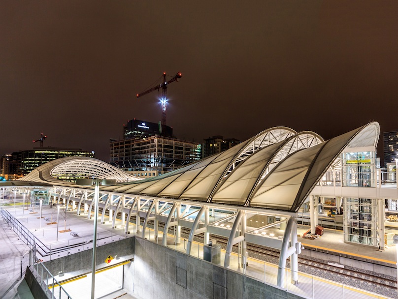 Image: Ryan Dravitz Photography
Building Team:
Owner: Denver Union Station Project Authority, Denver
Owner's Rep: Trammell Crow Co., Denver
Architect: Skidmore, Owings & Merrill LLP, New York
*Structural Engineer: Skimore, Owings & Merrill LLP, New York (Submitting firm)
General Contractor: Kiewit Building Group, Inc., Englewood, Colo.
Fabricator: Schuff Steel, Phoenix (AISC Certified Fabricator and Advanced Certified Steel Erector)
Consultant: AECOM, Denver
Denver’s historic Union Station is a Beaux Arts landmark located on the edge of the city’s central business district. SOM was commissioned to expand and transform this station and the surrounding 14 city blocks into a major regional transportation hub.
SOM structural engineers, working closely with SOM architects, designed the Commuter Rail Train Hall structure, Light Rail (LRT) station platform canopies, several additional steel-and-fabric pavilions, a pedestrian bridge, and a variety of other steel-and fabric canopy structures, all part of the greater Denver Union Station Intermodal Hub, which opened in Spring 2014.
The Train Hall structure is the focal point of Denver Union Station and was conceived as an efficient and formally expressive means of clear-spanning 180 ft across multiple railway tracks. The structure is a rational response to a series of programmatic requirements and constraints. The result is a steel-and-fabric canopy that rises 70 ft at the head-end platform, descends in a dynamic sweep to 22 ft at the center, and then rises again at the far end over an important pedestrian link across the site between Lower Downtown and the Central Platte Valley. The Train Hall’s stunning oculus form creates a new structure that is functional, contemporary, and contextual; a new grand civic space for the city of Denver.
The primary structural system consists of 11 steel arch trusses spanning nearly 180 ft from a single large-diameter pin connection atop 18-ft-tall arched column supports. The arch-trusses behave as their name implies: in-part like a truss, and in part like an arch. Each truss is stabilized by bracing struts between trusses. In the central region of the train hall, the arch-trusses are replaced by cantilevered trusses. Each truss is supported about 20 ft above the ground by a series of steel “kick stands,” which support vertical loads and horizontal thrust. Each kick stand is rigidly connected to the foundation with heavy anchor bolts. The arch-trusses and cantilevered trusses support a tensioned PTFE fabric.
Though the overall geometry of the train hall is a complex, seemingly free-form series of curves, the realization of this geometry was achieved by using only members curved to one circular radius. The curving tube members forming the complex shape of the inner oculus, for example, are comprised of tubes curved in single plane and then rotated in space to form a more complex 3D curve. The geometry of each arch truss, likewise, is defined by just two radii. The rationalized geometry approach allowed the geometry to be conveyed in simple two-dimensional plans and elevations, without the need for either three-dimensional work point schedules or exchange of electronic models. Keeping the geometry definition simple and rational was intended to allow many standard steel fabricators to bid for the work.
Further cost-reduction was achieved by responding to the fabricator’s concerns regarding the blanket designation of “Architecturally Exposed Structural Steel” (AESS) that would usually be applied for structures of this type. Rather than simply applying this requirement to all of the exposed steel, the architects and engineers identified only those aspects of AESS that were critical to the project’s success, and defined “exposed painted structural steel” (EPSS) requirements specific to the job. Remarkably, all the architectural steel at Denver Union Station was fabricated and detailed no differently than conventional structural steel.
The Light Rail Station is designed to appropriately address its specific function, ridership, and location within the larger network. Accordingly, the Light Rail Station required a design that was appropriately scaled to the size of the city. While the architecture of the station references the steel tubes and canopies of the Train Hall, these elements have been elegantly resized and reinterpreted to better suit the smaller, local ridership.
The Light Rail Station reveals the tremendous adaptability of the architectural language of Denver Union Station: Common material palettes and planning strategies unite the complex, while highly strategic rescaling encourages a range of character for individual spaces – from the grand and dynamic to the quiet and neighborhood-oriented.
The above-ground architectural steel structures for Denver Union Station are all composed primarily of round hollow structural section (HSS) steel tubes supporting PTFE tensioned fabric. The exposed painted structural steel was fully detailed in close collaboration with the architectural team to develop a consistent architectural and structural vocabulary throughout the project. All structural connections were fully designed by the structural engineers. Every structural connection and member is both structural and load-carrying, and also an architecturally expressive element. As such, the engineers took great time and care to fully detail all members and connections in the contract drawings in order to fully control the design and evaluate aesthetics prior to the shop drawing phase. This work had the additional benefit of eliminating fabricator connection engineering time and cost. To keep the design within budget, the exposed connections were engineered to use only conventional structural steel fabrication techniques and materials but took great care to shape the connections to be aesthetically minimal and consistent. All exposed structural steel is painted white with a high-performance coating system consisting of a shop-applied zinc-rich primer and a Polysiloxane finish coat. All steel work was blast cleaned to ensure the longevity of the coating system. The resulting design conveys a clean, modern machine-like aesthetic, without the use of expensive custom castings.
One of the largest of its kind in the U.S., this major city-building undertaking required close collaboration between visionary community advocates, a community-crafted master planning process, four governmental partners, a consortium of local developers, and the support of the federal government. This project sets a new standard in the U.S. for delivering on the highest aspirations for sustainability as both a means and an end: an integrated, LEED Silver-certified transportation hub as the heart of a vibrant, thriving community that is transit-served, economically robust and advancing the quality of life for Denver residents, workers, and visitors.
Merit Award: Circuit of the Americas Observation Tower and Austin 360 Amphitheater, Austin, Texas
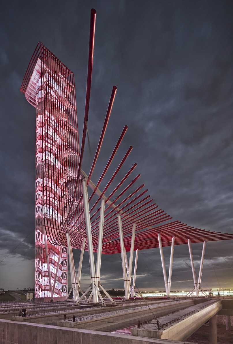 Photo: Paul Finkel
Building Team
Owner: Circuit of the Americas, Austin
Owner's Rep: MBC Consultants, Terrell, Texas
Architect: Miró Rivera Architects, Austin
*Structural Engineer: Walter P Moore, Austin (Submitting firm)
General Contractor: Austin Commercial L.P., Austin, Texas
Fabricator: Patriot Erectors, Inc., Dripping Springs, Texas
Bender/Roller: Chicago Metal Rolled Products, Chicago
Capturing the energy of Formula 1 racing in its iconic form, the 250-ft-tall observation tower provides a dramatic focal point for the Circuit of the Americas and a new landmark for Central Texas. The tower was conceived as a visual finale to the central Grand Plaza as well as a dramatic and memorable backdrop to the Austin360 Amphitheater. Evoking the notion of split-second speed, the tower’s unique design anchors visitors’ experience of the complex, fostering a sense of memory and place that is essential to the circuit’s identity. Circuit of the Americas is the first purpose-built Formula 1 racing facility in the U.S., and hosts not only the U.S. Grand Prix but also MotoGP, V8 Supercar, The Summer X Games, TEDxAustin, and Formula Sun Grand Prix, a collegiate competition for solar powered cars.
Carved into the topography of the site in order to enhance acoustics and views of performers, the Austin360 Amphitheater is the largest outdoor stage in Central Texas, with 6,671 fixed seats and a total capacity of over 14,000 people. The dramatic backdrop of the 251-ft-tall observation tower serves as a memorable setting, galvanizing the city of Austin’s reputation as the “Live Music Capital of the World.”
Inspired by the image of red streaks of glowing light that tail lights leave behind in the dark, a fan of red steel tubes over the amphitheater stage converges to form a veil that sweeps up and over a central elevator shaft wrapped by a double-helix stair. While code requirements required an enclosed shaft, the elevator core is gypsum and provides no structural support. The entire structural system is steel and is exterior to the shaft. Seemingly suspended from this pipe steel canopy is a viewing deck that offers a sweeping panorama of the entire track, downtown Austin, and the nearby Hill Country from an elevation of 230 ft.
The construction of the observation tower represents the successful integration of the unique qualities of steel in a project that required speed of construction, efficient structural design, and elegant aesthetics. Taking advantage of code egress requirements, the designers arranged the two access/egress stairs in a double-helix configuration; by using continuously welded plate for the treads and risers, each stair run was effectively transformed into a helical continuous diaphragm. The resulting stiff backbone allowed for a layered diagrid of hollow structural section (HSS) tubes at the perimeter of the tower to be employed as a combined gravity and lateral load system. Inside the stairs, a standard cold-formed steel and gypsum board system frames the elevator shaft. The filigree-like diagrid perimeter consists of multiple small, distributed members that contribute the necessary overall strength by number rather than individual brawn. Immediately outside of the stair stringers is a layer of diagonally oriented HSS 3x3 members; stacked outside of these diagonals is a layer of vertical HSS 4x4 columns. The diagonal and vertical HSS layers combine with the stair stringer diaphragms to form a fully braced tube. Eccentricities between the layers are handled by resolving a couple into the interior stringer through carefully detailed steel connections. By dissolving the diagrid frame into multiple small members, demands on individual connections are limited and can be handled with economical details.
At the top of the observation tower, the side faces of the diagrid skeleton extend outward to form a deep cantilever truss that supports a 900-sq-ft viewing deck. The entire balustrade and a portion of the floor is structural laminated glass, allowing more daring visitors to look 230 ft straight down beneath their feet. From above this level, the veil of closely spaced round HSS 8.625 tubes cascades down the front of the tower. A striking visual feature, the veil is also an outrigger column for lateral load resistance via a series of struts and rods that connect it to the main tower.
The veil extends over the amphitheater stage to form the top chords of the nine primary trusses of the amphitheater stage roof. The stage is covered by a transparent single layer ETFE membrane with integral stainless steel cables just above the plane of the truss top chords. Between each truss chord are two additional infill pipes to match each member of the tower veil and enable the veil to extend out over the stage. The infill members are connected to the truss top chords by a checkerboard of HSS 6x4 that both support the infill members and develop a horizontal Vierendeel diaphragm. The primary structure supports a 140,000-lb. concert rigging grid integrated at the bottom chord level of the trusses and accessed via a front-of-stage catwalk system.
Including all structural steel, floor plating, railings, and connections, the observation tower and stage roof contain approximately 535 tons of steel.
Final approval for the tower concept was granted less than a year before the first race, and if the tower was going to be built, it had to be complete before the first race. Engineering, fabrication, and erection had to occur inside an extremely compressed timeframe. The engineer worked with the steel erector to establish preferred strategies, shop module sizes, and connection details. Because of the tight schedule and the complexity of the structure, traditional paper drawings were not a practical solution as a final deliverable for construction. The structural engineer produced a fully connected Tekla model (BIM LOD 400) that was then transferred to the detailer, which produced fabrication shop drawings directly from the model. The project’s general contractor estimated that this process saved three months over traditional delivery methods.
Merit Award: Landscape Evolution Observatory at Biosphere 2, Oracle, Ariz.
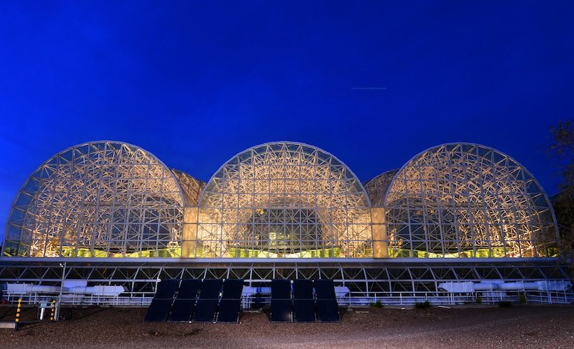 Image: Erik Hinote
Building Team
Owner: The Univesrity of Arizona-Biosphere 2, Oracle, Ariz.
Owner's Rep: University of Arizona, Planning Design and Construction, Tucson, Ariz.
*Architect: M3 Engineering and Technology, Tucson, Ariz. (Submitting firm)
*Structural Engineer: M3 Engineering and Technology, Tucson, Ariz. (Submitting firm)
General Contractor: Lloyd Construction, Tucson, Ariz.
*Fabricator: Parsons Steel Builders, Tucson, Ariz. (AISC Certified Fabricator and Erector) (Submitting firm)
Detailer: M3 Engineering and Technology, Tucson, Ariz.
*Erector: Parsons Steel Builders, Tucson, Ariz. (AISC Certified Fabricator and Erector) (Submitting firm)
Consultant: Tractel Ltd., Swingstage Division, Scarborough, Ontario
The University of Arizona, in the search of understanding nature and the different mechanisms that occur in the landscape, has built the Landscape Evolution Observatory (LEO) at Biosphere 2, just north of Tucson, Ariz. This $6.7 million experiment is the world’s largest weighing lysimeter for the study of the interaction of water, temperature, soil, and vegetation, among other environmental elements, on three full-size-scale hillslopes. With the use of the lysimeter, a measuring device used to quantify the amount of water released through evapotranspiration by changes in weight, in this case using 10 large uniaxial load cells per hillslope, LEO enables officials to quantify interactions among hydrologic, geochemical, geomorphic ecological, microbiological, and atmospheric processes associated with incipient hillslope development.
Each of the three identical hillslopes that form LEO, are uniquely constructed of large steel planting tray structures, built inside an existing large space-framed greenhouse, previously used for intensive agriculture, and anchored over an existing elevated concrete floor structure.
A steel-only structure option was selected from three concepts as the most financially and technically feasible option, given the existing building spatial limitations, the structural constraints set by the existing concrete structure that frames the basement, and the need for construction flexibility.
Three sections form the hillslope steel structures:
Tray - The tray is a 38-ft-wide x 100-ft-long x 3.3-ft-deep steel box open on the top, sloping 10 degrees in the longitudinal direction with a changing transverse slope along the tray’s length to form the ridges and a valley channel that simulates a hillslope. To form this compound slope, the tray is built with transverse U-shaped frames of wide-flange beams, spaced at 1 meter on center to match the sensor grid spacing, thus resembling the ribs of a ship’s hull structure. All the transverse wide-flange beams are attached to two deep longitudinal wide-flange girders that connect to the substructure. Each tray is clad on the bottom and all interior four sides with 3-in.-deep steel N-deck, fiber-reinforced cement board and a special waterproofing membrane to contain a one-meter thick layer of finely crushed basalt, irrigation water, and a complex array of 2,847 different sensors per tray.
Substructure - The substructure is a system of wide-flange beams and double angle steel braces that connect to 10 hollow structure section (HSS) columns aligned directly over existing concrete columns of the basement structure, supporting the tray through 10 load cells centered on the top of each column.
Personnel Transporter - The personnel transporter is a mobile steel structure similar to a gantry crane for human transport that traverses over the tray, covering its full width and length, and allowing scientists to monitor LEO without disturbing the soil.
The load cells, which have the capacity to measure up to 330,000 lbs., with the accuracy to detect a change in water weight equivalent to a layer of 1 cm of water (about 2 lbs/ft^2) over the tray, are rigidly attached on their lower end to the column cap plates and have a special self-centering pinned connection at the top, which minimizes the overall moment transferred to the load cell and the size of the related connection at its base. The use of these load cells required tighter construction tolerances than standard steel construction, thus making the construction quality control more challenging. The original intent during design was to use temporary spacers for load cells until the steel structure was placed in position. However, the contractor recommended that the spacers continue to be used until all welding was complete to avoid affecting the load cells during the construction. Furthermore, before the construction started the steel fabricator proposed the addition of a jacking system at the top of each column to facilitate the exchange of the load cells for temporary spacers once the soil was loaded.
Laser scanning technology was used to recreate a model of the existing building and determine more accurately the dimensions of the construction available space, which helped enormously in finding possible clashes and designing items such as the personnel transporter. This technology allowed the designer to maximize the use of space and reduce or eliminate costly modifications during construction. Additionally, steel shop drawings were developed using Tekla Structures as part of the design documents, saving money and time during the construction phase as the detailing complexity and any clashes were solved during the design phase. The model used to generate the detailed shop drawings was used to quantify materials and helped the steel fabricator understand the complex structures in a more efficient way before starting fabrication. The advantage of using BIM technology was evident in the reduced amount of RFI’s and almost-null field changes, which potentially could have happened in a larger quantity given the complexity of the project and its tight 16-month schedule.
The personnel transporter idea originated with a need to mobilize scientific staff over the surface of LEO without affecting the soil or its content. Many ideas were explored before a special consultant and the engineer of record arrived at the use of a technology similar to that used for window washing.
The space dedicated to LEO has only one direct entrance from the outside, measuring 10-ft wide x 12-ft high, which required the design of most of the field connections be bolted for ease of field construction as well as to set a limit on the size and weight of pieces that were transported to the construction site. The steel fabricator created a special transporter to introduce the steel pieces into the LEO space.
Merit Award: Minnesota Fallen Firefighters Memorial, St. Paul, Minn.
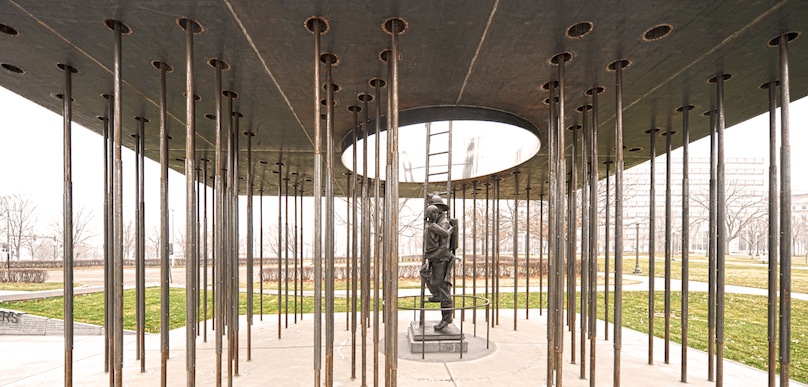 Image: Bill Baxley
Building Team
Owner: Minnesota Fire Service Foundation, Eden Prairie, Minn.
*Architect: Leo A. Daly, Minneapolis (Submitting firm)
*Structural Engineer: Leo A. Daly, Minneapolis (Submitting firm)
General Contractor: Meisinger Construction, South St. Paul, Minn.
A new memorial on the state capitol grounds in Saint Paul honors the sacrifice of Minnesota firefighters killed in the line of duty. The memorial houses the Minnesota Firefighter Memorial Statue, previously on display at Minneapolis‐Saint Paul International Airport.
The ground rises to present visitors with a cast stone-faced wall inscribed with names of fire departments from throughout the state. A large steel monolith hovers above the focal point of the site where the statue stands, forming a pavilion to mediate between the monumental scale of the capitol grounds and the life‐scale of the statue. A field of many light steel columns supports the weight of the monolith above; names of the fallen are inscribed on the columns. Visitors move in the shadow of the monolith through the multitude of columns to encounter the statue, bathed in light from a mirrored void in the monolith above. Outside the pavilion a wood bench provides a comfortable place for reflection.
The basic design requirement was that the site needed to be a living memorial - in its materiality, organization and pattern of use. Minnesota needed a place to honor its fallen fire fighters while providing a place for contemplation reflecting the nature of the fire service.
This project demanded a large public dedication ceremony, whose planning took the duration of the construction and drove the tight project schedule. The entire construction period was five months from contract award to final completion (from May to September 2012), requiring responsiveness of the design team and contractor to collaborate quickly and effectively.
The overall project budget was $600,000. The project was bracketed by a fundraising kickoff and the eventual dedication ceremony, creating a tight schedule for design, fundraising, event planning, and construction. The design team needed to be able to quickly respond to the fundraising needs, reviews by the state, and ongoing revisions to the list of names included in the memorial.
The weathering steel of the monolith presents a rich patina, evolving in a slow process analogous to the rapid oxidation of fire. The organizing grid of 100 potential columns embodies a repeating century of years - 10 decades by 10 years per decade. Currently an incomplete constellation of 86 columns are present, recording the years in which Minnesota firefighters have died in the line of duty. Over time the assemblage will accumulate additional inscriptions, and new columns will appear as future firefighter deaths occur in years not yet plotted. The increasing multitude reflects the ongoing sacrifice of Minnesota firefighters.
The structural challenges lay in two arenas: creating a monolith of plate that can be supported by a series of columns and designing the slender columns. The monolith was solved by coordinating with the architects the column‐to‐monolith connection. The connection contained a pipe‐sleeve which joined the upper and lower faces of the monolith. This sleeve allowed the column to support both surfaces and also joined the two surfaces. The slender columns were made stable by designing the base and the top connection to be fixed. The foundation was designed as a mat slab to accommodate the nontraditional column layout and this further accommodated a fixed base plate connection with pre-tensioned bolts. The sleeved connection at the top of the column allowed fixity in that it accommodated a spanning knife‐plate. The plate’s short span in conjunction with the sleeve’s engagement of both planes were stiff in both bending and torsion.
The demanding schedule was answered in two ways. First, contractors and specialty fabricators were involved in the design process. This allowed the design team to integrate their input and create a design that was assured to be quickly and accurately fabricated and then erected. Second, technology was leveraged to manage received information from both owner and constructors, to document design information, and then to convey the compiled information to the constructors in such a way that facilitated the process.
The design team provided the owner regularly updated imagery that aided the fundraising efforts, was used in presentations around the state, as well as on social media platforms to keep stakeholders, contributors, and the public in the loop with current information.
The memorial project could only have been fashioned in a digital world. At first glance it doesn’t appear that way - it is fairly simple looking, small in scope, built with low‐tech materials. Its tactile, rich, and variable surfaces feel analog in a way that belies and transcends its digital underpinnings. Hidden within its apparent simplicity is a complex organization, generated by various sources and translated into form through a variety of information flows.
Not only were typical software packages used for inputs and outputs of information - AutoCAD, Excel, Revit - but graphic design technologies were leveraged for fabricating key elements of the memorial. The fluidity with which software now transfers information was instrumental in bringing all the pieces together to form the whole.
One aspect of the project where technology enabled success was with ongoing updates to the list of names to be memorialized. As the researcher discovered more about specific line-of-duty deaths and confirmed public records and fire department histories, the list of names grew and many spellings changed. The design team was able to take the “living” Excel spreadsheet document and incorporate it into the design on the fly through a link with BIM, enabling our verification process to proceed in parallel with the overall design.
The project demanded a high level of quality because of its high visibility on the state capitol grounds. The specialty contractor which fabricated the memorial met standards that exceeded those for architecturally exposed structural steel (AESS). Digital submittal and review of shop drawings enabled exportation of information into AutoCAD from Revit and Adobe Illustrator that was then used by the contractor for precision laser cutting, CNC milling, and cutting of masks for sandblasting inscriptions.
Merit Award: Hilton Columbus Downtown High Street Bridge, Columbus, Ohio
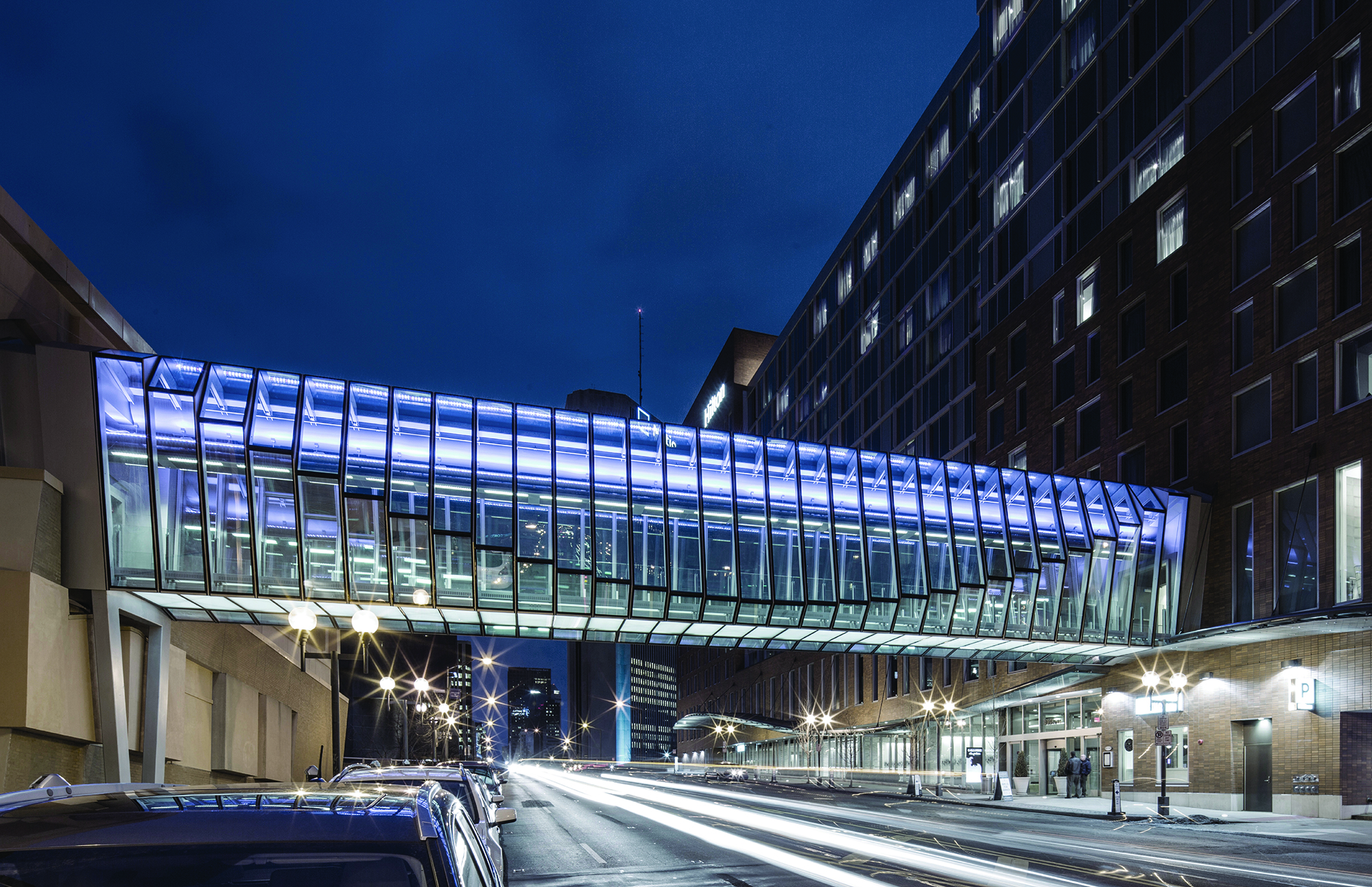 Image: Macbeth Photo
Building Team
Owner: Franklin County Convention Facilities Authority, Columbus, Ohio
Owner's Rep: Strategic Advisory Group, Dulut, Ga.
*Architect: HOK, Chicago (Submitting firm)
*Structural Engineer: Halvorson and Partners, Chicago (Submitting firm)
General Contractor: Turner/Smoot joint venture, Columbus, Ohio
The Hilton Columbus Downtown High Street Bridge is a 105‐ft‐long enclosed glass walkway, with a construction cost of $4.5 million. The unique pedestrian bridge connects the new Hilton Hotel with the adjacent Greater Columbus Convention Center. Entirely supported by a single overhead steel tube and suspended ribs, the all‐glass bridge’s design emphasizes physical and material lightness and visual transparency to join user and pedestrian; purposefully avoiding the external, heavy truss pedestrian bridge aesthetic found throughout the city.
To reinforce the concept of physical and visual transparency, glass is employed as the primary material for the floors, walls, and entire enclosure of the bridge. Emphasizing daylight and views, the bridge’s glass and lightweight steel composition utilizes a unitized module that was fabricated and shipped as small components that were then assembled and glazed on site prior to lifting the entire structure into place. All building services, including air, water and lighting, are delivered through the overhead 48-in. steel tube or discretely within the glass walkway.
The bridge design is both programmatic and symbolic in intent as the new physical gateway to the city of Columbus from the north, extending the Short North neighborhood iron trellis arches into downtown.
The design team studied many options for the main 100-ft span pedestrian bridge before developing the final structure that would provide the most efficient form and one that the team, client and city would agree upon. A series of bent “fin” frames hang down from a central pipe spine atop the walkway to support a glass floor with light steel framing; this central pipe spans from a haunch on the new hotel to an inverted A‐frame added to the existing convention center, on a new caisson.
There were a number of details the team worked out in order to design and ultimately build this structure: The team analyzed and designed the entire structure for this unique bridge, including careful assessment of local stresses at the fin‐to‐pipe connections and detailing pipe‐end connections for large forces and required movements. In fact, the bridge design was controlled by limiting movement and deflections. The 48-in.-diameter pipe resisted vertical loads, and worked together with diagonal cable bracing in the glass floor plane to resist lateral and incidental torsion. The interface of the main span bridge and hanging bridges at and through the existing convention hall also required significant review and coordination, as did detailing for tolerances of the old and new system.
The design and construction of the bridge posed many challenges and opportunities for the design firm and contractor to collaboratively work through together to overcome. The design process utilized 3D BIM modeling to improve coordination of mechanical electrical and plumbing systems and to quickly and accurately illustrate steel and glass connection detailing. This same BIM modeling process allowed the design team to coordinate effectively with the construction team and reduce design to fabrication time.
The 138‐ton bridge spanned 105 ft across High Street, the main thoroughfare through downtown Columbus, therefore an extended shut down of this roadway was not an option. The design and construction teams came together to develop alternative methods of construction that would maintain the design intent and integrity, while allowing the bridge to be primarily pre‐constructed in an on‐site location adjacent to its final resting place. The most beneficial alternative solution included modification of some welded connections to bolted connections, which aided on‐site preassembly. The bridge structure was pre‐assembled, pre‐painted and pre-glazed on site prior to hoisting. The hoisting operations took place over one weekend and the shutdown of the roadway was limited to a two-day time period, greatly minimizing the impact to city traffic flow.
Maximizing the height of the interior space of the bridge, which was critical to the design intent and end-user satisfaction, was another challenge overcome collaboratively by the design and construction team. The overhead MEP services feeding the chilled beam, the lighting and the fire protection for the sky bridge were too large to fit in the allotted space to maintain the desired height. The design and construction teams worked creatively to coordinate, resize, reroute and maximize the overhead space to allow for the designed clear interior height. One of these strategies was to route ventilation ducts through the overhead 48-in. steel tube “spine,” thus saving precious head-room height.
Projects $15 Million to $75 Million
National Award: Florida Polytechnic University Innovation Science and Technology Building, Lakeland, Fla.
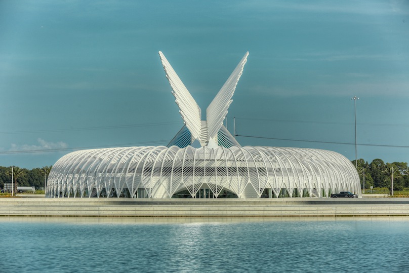 Image: Macbeth Photo
Building Team
Owner: Florida Polytechnic University, Lakeland, Fla.
Owner's Rep: Lighthouse Advisors, Tampa, Fla.
Architect: Santiago Calatrava, New York
Structural Engineer: Thornton Tomasetti, Newark, N.J.
General Contractor: Skanska USA Building, Tampa, Fla.
*Fabricator: E & H Steel Corp., Midland City, Ala. (AISC Certified Fabricator) (Submitting firm)
Detailer: Dowco Consultants Ltd, Surrey, B.C.
Erector: Midwest Steel, Detroit (AISC Advanced Certified Steel Erector)
Florida Polytechnic University, Florida’s newest university and only one dedicated to a curriculum of science, technology, engineering and mathematics, started its new campus building program with the 162,000-sq.-ft Innovation Science and Technology Building designed by world renowned architect Santiago Calatrava. This two-story reinforced concrete structure’s signature element is the 250-ft-long glass atrium shaded by 94 operable louver arms all of which are supported by structural steel boxed plate assemblies spanning up to 72 ft.
The box plate assemblies are designed to carry not only the load of the glass atrium but also the extreme loads of the shading system’s operable louver arms, which are as long as 62 ft. The louver arms move during the day to act as sun shades. The arms are attached to a structural steel plate stanchion that is field welded to the structural steel plate box assembly. The load is transferred by the box plate assemblies and network of internal plate stiffeners to the foot assembly and then to a reinforced concrete ring beam.
The structural steel box assemblies were shop fabricated then most were shipped in two pieces due to length and joined in the center at the job site. The lower portion of the plate assemblies are architecturally exposed structural steel (AESS) and exposed to view from the grand hall below. The AESS element has such a smooth finish that most observers mistake this structural steel for another building material.
Merit Award: University of Oregon Hatfield-Dowlin Football Performance Center, Eugene, Ore.
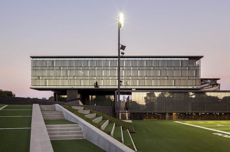 Image: Jeremy Bittermann
Building Team
Owner: University of Oregon/Blue Ribbon Sports, Eugene, Ore.
Architect: Zimmer Gunsul Frasca Architects LLP, Portland, Ore.
Architect: Firm 151, Portland, Ore.
*Structural Engineer: KPFF Consulting Engineers, Portalnd, Ore. (Submitting firm)
General Contractor: Hoffman Construction Company of Oregon, Portland, Ore.
Fabricator: Metals Fabrication Co., Airway Heights, Wash. (AISC Certified Fabricator)
Detailer: Tru-Line Drafting Services, Surrey, B.C.
As an elite and innovative college football program, the University of Oregon is constantly advancing the state-of-the-art for athletics. The newest campus addition, the privately funded 145,000 sq.-ft Hatfield-Dowlin Football Performance Center, has further empowered the already formidable Ducks with groundbreaking facilities to help ensure the high-flying program maintains its competitive edge. Made possible by the generous contributions of donors, notably Phil and Peggy Knight of Nike fame, whose mothers are the namesakes of the facility, the complex is intended to serve as a lasting legacy to ensure the continued success of Oregon athletics.
The architecture makes a clear proclamation of strength and innovation, and opposing teams and fans cannot help feeling intimidated by the dramatic cantilever looming overhead on the approach to Autzen stadium, which stands as a bold testament to the strength of the program, as well as of the structural steel that supports it.
Mirroring the efficiency and precise design of Oregon’s hallmark “Blur” offense, the complex provides worldclass training, teaching, office, and nutrition services to the team and staff, all wrapped in a sleek exterior. Once inside the facility, one can quickly navigate to the impressive weight room, coaching staff offices, team meeting theaters, position-specific training rooms, locker rooms, practice fields, dining facilities, the futuristic “war room”, and the eminently welcoming player’s lounge, which prominently features exposed structural steel. The layout allows players and staff ample opportunity to work, learn, share, and recuperate, all right on the doorstep of Autzen stadium, where all their hard work comes to fruition for the enjoyment of the roaring crowds.
A football program that demands excellence from its players and staff deserves no less from its facility, and the project design team worked tirelessly to ensure the complex would be peerless. Steel played a key part in the major features of the complex, including floor cantilevers of up to 50 ft, the precise edges of the exterior steel-clad player’s walk bearing the engraved name of every football letterman in university history, the exposed full story steel trusses, and an impressive and intricate façade. Similarly, throughout the myriad of sleek, smaller-scale custom design features, including minimalist railings, high-tech lockers, hanging bathroom mirror attachments, legless built-in seating, and stretching rails, the design team strove to develop the most attractive, efficient, and best performing design possible, which time-and-again meant utilizing the strength and flexibility of steel.
The most structurally innovative and challenging building component of the three that make up the complex is the three-story “Office Bar” structure housing the coaching staff and recruiting offices along with the players’ lounge. It hangs suspended approximately 40 ft above the plaza below, hovering over the players’ walkway heading to the practice fields. The 35-ft-wide building is approximately 235 ft long and is supported only by two steel-clad stair cores with plan dimensions of 22 ft x 12 ft and 22 ft x17 ft, occurring near the ¼ point from each end, with cantilevers of 50 ft and 40 ft extending out at the north and south ends, respectively, and a central span of almost 120 ft. The primary structure of this long, slim suspended building is composed of a pair of full-story deep steel warren trusses located along the east and west edges of the uppermost level. The exposed W12 truss diagonals make an impressive pattern along the full length of the player’s lounge, while the fully-welded connections allow for the cleanest appearance possible as the diagonals disappear into the floor and ceiling. The lower two floors are hung from the trusses using high-strength steel rods, allowing for column-free space throughout the building, with maximum transparency along the fully glazed west face, which directly overlooks the new practice fields.
The Office Bar trusses are located outboard of the concrete stair cores by up to 6 ft, 6 in., demanding significant outrigger beams to deliver the truss reactions to the concrete core. Continuous 30-in. deep built-up steel beams running continuously between the trusses were cast into the concrete core walls to provide a strong and resilient load path. A 24-ft-wide steel-framed sky bridge connects the east side of the office bar to the adjacent teaching box building at levels 4 through 6, just south of the northern stair core. The wide diagonal-free opening near the end of the central truss span is accomplished through the use of a three-story tall Vierendeel truss composed of fully welded W30 steel members, connecting to single-story warren trusses on each side. The unique appearance of the Office Bar is further augmented by the “sunglass wall” on the west face, composed of a series of intermittent exterior glass panes alternating position in three planes, providing a dynamic appearance while providing sun-shading to the building occupants. This defining feature is held off from the building skin by several feet, hanging from cantilevered hollow structural section (HSS) beams that extend off of the roof, providing a significant expression of dimensionality and creating fantastic shadow patterns.
The Teaching Box building is the largest building mass with five full stories at approximately 100 ft x160 ft, accommodating the lobby, dining hall, media and scouting facilities, locker room, position classrooms, meeting rooms, and the team theaters. The building features a two-story tall 28-ft cantilevered portion at levels 4 and 5 on the east side, hung from 5-ft deep custom steel plate girders at the roof. The upper three levels of the building are framed primarily with composite steel beams and columns, all analyzed for vibration considering the weight of occupants present in the football program facility to ensure excellent performance.
The building’s unique and highly variable façade includes a plethora of varying support and loading conditions that required attention and coordination. Numerous vertical and horizontal projections occur around the building, supported by cantilevered HSS framing extending out from the primary structure, allowing for a significant degree of three-dimensionality in the building skin, enhancing the dynamic appearance of the building.
Merit Award: Pomona College, Studio Art Hall, Claremont, Calif.
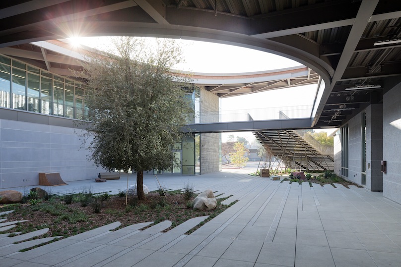 Photo: Jeremy Bittermann
Building Team
Owner: Pomona College, Facilities and Campus Services, Claremont, Calif.
*Architect: wHY Architecture, Culver City, Calif. (Submitting firm)
*Structural Engineer: Thornton Tomasetti, Los Angeles (Submitting firm)
General Contractor: Hamilton Construction, Pomona, Calif.
Fabricator: Anvil Steel Corp., Gardena, Calif. (AISC Certified Fabricator)
The new steel-framed Studio Art Hall at Pomona College, one of the nation’s leading liberal arts colleges, replaces the century-old Rembrandt Hall, which housed the college’s art program. Because the art department not only caters to art majors but the entire student population, the college needed a space that would influence and captivate anyone who stepped through its doors.
The art hall is a haven of creativity, artistry and connectivity. Situated near the heart of campus, the two-story, 35,000-sq.-ft interdisciplinary art center embodies a contemporary way of thinking, creating and influencing art and culture. The layout is designed to inspire interaction, discussion and socialization while moving through the studios and public areas. The monumental staircase draws visitors into the space and provides an informal seating area to meet or socialize. With sweeping views of the San Gabriel Mountains and historic oak grove framed through floor-to-ceiling windows, the art hall reflects its surroundings in Claremont, Calif., and draws inspiration from the expansive natural views.
Built to LEED Gold standards, the hall was designed with a green, minimalist approach by remaining open and airy with free-flowing spaces and external hallways. The central courtyard is open to the sky, providing ample lighting and yet another connection to nature and the elements. Six sloped roof skylights with vents allow natural lighting and airflow throughout the studios.
Completed in October 2014, the $29-million hall exemplifies the beauty and integrity that only comes from a hardworking, dedicated and collaborative team. Thornton Tomasetti, wHY ARCHITECTURE and Hamilton Construction collaborated extensively on this design-assist project. Throughout the project, Thornton Tomasetti reached out to Hamilton and wHY at various milestone markers to address deliverables. A stop-and-go approach allowed changes to be made throughout the process while monitoring the project budget and making adjustments to the design for cost and time savings.
Prior to designing the hall, wHY held its Ideas Workshops for the Art Department faculty and students where the entire art program and site was reimagined. From these sessions, a common thread was the need for cross-pollination of ideas which resulted in wHY’s use of semi-public “grey spaces” such as the open courtyard in the heart of the building. Input from the art department did not stop there either. When steel framing mock-ups for the roof were created on-site, faculty voiced their opinions of how the secondary wood framing would alter their vision for the aesthetics of the roof. wHY and Thornton Tomasetti went back to the drawing board and created a different design that ultimately saved on construction costs while also staying true to the faculty and wHY’s vision. From foundation to finish, the entire construction process was streamed live for viewers to watch as the construction progressed over of the course of almost two years. A time lapse was later created by Hamilton Construction and can be seen here: http://www.youtube.com/watch?v=0fmjt4UkX6I.
The art hall’s arching steel and wood roof appears to float above the building, mimicking the ebb and flow of the surrounding mountains. To create an undulating shape, most of the steel used in the roof’s framing was set at 45-degree angles with respect to the column grids. The curvature in one direction was developed by straight lines of beams at a constant elevation within the same line; while in the perpendicular direction, the curved geometry was achieved by faceted beam lines. The result is a steel diagrid with 3x10 sawn-lumber joists spanning between the beams to support the roofing system. A more common approach to designing the roof would have been to curve all the steel members, however angling the steel allowed for a minimum amount of curved members and reduced fabrication cost and time. Angling the beams required custom connections to accommodate multiple beams (up to eight in some areas) meeting at one connecting point in the diagrid. Some segmented beams have moment connections to support cantilever conditions or longer spans where additional stiffness was needed by using two-way action.
The complex geometry of the roof canopy was rationalized and documented using Grasshopper, a parametric toolbox incorporated in Rhino that enables designers to define and manipulate the intricate geometric shapes. The curved roof geometry was represented by a series of compound curves, steel elevations and rotation angles which were conveniently obtained with Grasshopper.
Entirely exposed from below, the roof framing design focused on the steel aesthetics by minimizing imperfections and using high-quality finishes. The exposed steel was intended to be built to similar standards as architecturally exposed structural steel (AESS). However, in order to keep the steel fabrication and erection costs within the initial budget, it was not specified as an AESS structure. Instead, wHY and Thornton Tomasetti prepared custom details using tighter tolerances than usual and worked with the steel detailer to ensure neither fabrication nor erection were impacted. These efforts resulted in a steel-tonnage rate similar to non-AESS structures. Coordination with the contractor was also crucial. To minimize the potential for field fitting issues, the contractor and trades ensured installation was done properly and the steel remained unblemished.
The art hall’s design was a 180-degree turn away from the campus’ existing traditional Spanish mission-style structures making it a signature building on campus for students, faculty, alumni and the public to visit for years to come. Every detail of the art hall was thoughtfully and carefully designed and constructed to create an iconic structure that is sure to inspire all who walk through its doors.
Merit Award: Central Arizona College, Maricopa Campus, Maricopa, Ariz.
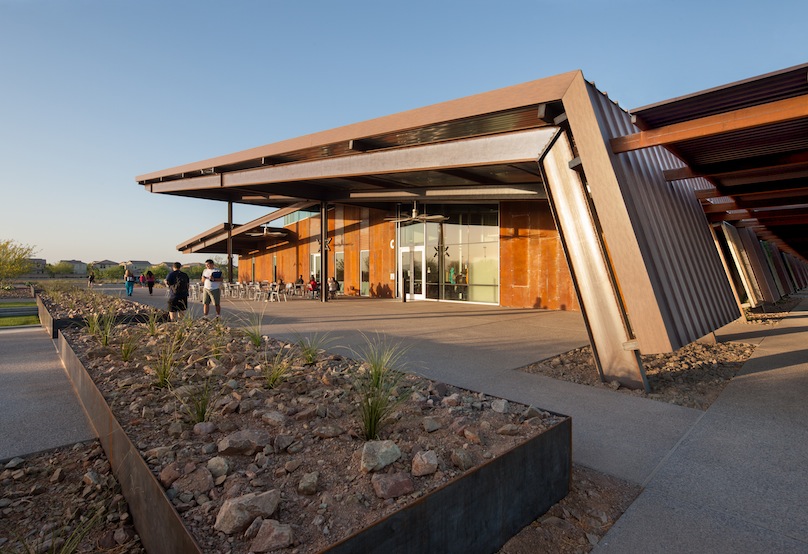 Image: Bill Timmerman
Building Team
Owner: Central Arizona College, Coolidge, Ariz.
Owner's Rep: Central Arizona College, Finance and Administration, Coolidge, Ariz.
*Architect: SmithGroupJJR, Phoenix (Submitting firm)
Structural Engineer: PK Associates, LLC, Consulting Structural Engineers, Scottadale, Ariz.
General Contractor: CORE Construction, Phoenix
Fabricator: S & H Steel Co., Gilbert, Ariz. (AISC Certified Fabricator and Erector)
Erector: S & H Steel Co., Gilbert, Ariz. (AISC Certified Fabricator and Erector)
Consultant: Dibble Engineering, Phoenix
This new ground-up satellite campus aims to create a unique and authentic identity for the growing Central Arizona College and to elevate its brand in the higher education marketplace while creating a highly sustainable prototype. Master planned for significant growth in the next 20 years, the campus is planned for over 700,000 sq. ft on 200 acres at full build out. Three academic buildings and a central plant were constructed on 28 acres as the initial phase, and create a campus design language for future development to follow.
Totaling over 76,000 gsf, the diverse program includes teaching laboratories, classrooms, culinary arts, a bookstore, library, learning center, interactive distance learning classrooms, student services, administration, and a multipurpose community room. This community room bookends the main entry with the library, acting as a beacon for the greater community and promoting education.
Rustic natural colors and weathering steel allow the buildings to blend beautifully with their surroundings. Rammed earth walls constructed of local Arizona soils uniquely frame the building portals accentuating the Arizona setting and mountain surroundings.
Long cantilevers highlight the steel design, providing both shade and outdoor student gathering space. Wide-flange steel shapes are tapered at the ends to provide an elegant and sleek look. Canted walls give the buildings a unique aesthetic while strategically blocking the southern sun exposure. Clearstory windows on the north side of the buildings allow natural light into the interior spaces, as do four large light scoops in the classroom and lab areas.
The steel structure is highlighted within the spaces, with many of the areas utilizing exposed structure rather than ceilings. Steel roof framing was constructed with a layered approach in mind to give the spaces a light and airy feel. Tube steel members were placed on top of sloping wide-flange steel girders to give the effect of the roof deck floating above the main structure, while allowing the metal deck flutes to run parallel to the main structure. This layered approach was also effective in reducing costs by allowing the use of long continuous members, thereby reducing the number of connections and costly associated welding. Connections were carefully designed to accomplish both functional load requirements while providing an appealing aesthetic appearance. Bolted slip critical moment connections were used to connect the sloping roof girders to the canted columns in a clean aesthetic manner. Steel moment frames are used throughout the structures to resist wind and seismic lateral loads, eliminating the need for shear walls or cross bracing members and enhancing the open inviting feel to the spaces.
Frosted vertical glass fins are cantilevered from a steel tube and “shoe” system, lending a contemporary accent to the building in beautiful contrast to the rammed earth walls, while providing critical sun shading from the Arizona heat.
Site structures complement the main buildings, where the theme of long steel cantilevers is again elegantly continued. The main walkway is covered by a 30-in. cantilevered roof canopy, constructed of sloping wide-flange steel beams supported by canted steel columns. The unique geometry and layered steel roof framing is continued on this walkway providing both continuity and function between the buildings.
The contractor truly fostered a culture of collaboration, communication, and coordination. On top of the weekly owner/architect/contractor meetings, the design team and engineers were invited to preconstruction meetings and ongoing subcontractor meetings. The contractor provided the necessary platform for the design team to communicate the design intent. Special coordination meetings were scheduled with representatives from the owner’s unique departments, i.e. audio-visual, library, etc. Expectations were set with subcontractors before submittals were developed, and the contractor rigorously issued confirming requests for information (RFIs) to make sure even the most minor items were not missed. The owner was always kept involved in project decisions. The team reviewed mock ups and made weekly site observations as a team of owner/architect/contractor.
Structures are conceived as a series of honest, spare and no maintenance “academic sheds.” Deep overhangs let interior academic spaces flow outdoors seamlessly. Corten steel and rammed earth create the primary exterior language, eliminating the need for long-term maintenance. Unpainted structural steel and galvanized acoustical decking create the main interior volumes, while continuous north facing clerestory glazing harvests daylight, coupled with numerous large daylight scoops.
The main campus entry acts as a beacon for the community, promoting education and community based activities. A new campus language is born out of its unique desert context, a model for the campus of the future. Each building strategically turns its back to the harsh desert southern sun, while harvesting northern daylight and creating a continuous shaded arcade on the south that connects the campus’ classrooms end to end. Thirty-ft overhangs create shaded outdoor student spaces adjacent to a newly crafted amphitheater. Large outdoor fans create air movement to enhance personal comfort. R-30 walls and R-40 roofs create a super insulated high-performance envelope. Rolling barn doors and minimal wall partitions organize interior volumes that are planned to be modular and easily removable when expansion and renovation occur in the future. Each instructional environment is offered diffuse day lighting via strategically located glazing and clerestory.
Projects Greater than $75 Million
National Award: The Vegas High Roller, Las Vegas
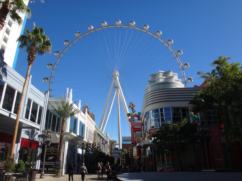 Image: Arup
Building Team
*Owner: Caesars Entertainment Corp., Las Vegas (Submitting firm)
Owner's Rep: Caesars Entertainment Corp., Las Vegas
Architect: The Hettema Group, Pasadena, Calif.
Architect: Klai Juba Architects, Las Vegas
*Structural Engineer: Arup, San Francisco (Submitting firm)
General Contractor (base): W.A. Richardson Builders, LLC, Las Vegas
Fabricator (base): SME Steel, West Jordan, Utah (AISC Certified Fabricator and Advanced Certified Steel Erector)
Erector (base): SME Steel, West Jordan, Utah (AISC Certified Fabricator and Advanced Certified Steel Erector)
Consultant: Leitner-Poma, Grand Junction, Colo.
The High Roller opened in March 2014, the largest observation wheel ever built at 550-ft high with an approximate cost of $300 million. Caesars Entertainment -- the owner -- wanted its observation wheel to not only be the largest in the world, but to offer its guests the best experience.
“Vegas demands audacity and ‘over-the-top,’” said Greg Miller, senior vice president of development for Caesars Entertainment “The High Roller is so much more elegant and beautiful than any other wheel. The creative intent was to have it appear to be lightweight, without a lot of structure.”
The Hettema Group was appointed as the concept design and ride architect. Early collaboration between the client, architect and Arup, the engineer or record, led to a structural scheme with minimal visual impact, affording passengers a “floating sensation” and sense of space. This was achieved with a single rim element and single cabin support bearing. Previous observation wheels, including the London Eye and Singapore Flyer, had wider truss rims and dual cabin bearings, restricting views from the cabin and making passengers more conscious of the structure supporting them.
Caesars’ intention for the High Roller was to attract passers-by from the Vegas Strip into their new LINQ development, a pedestrian- and family friendly retail, dining and entertainment area. The unique nature of the wheel demanded innovation in almost every aspect of design. Two particularly challenging design constraints of the established design criteria were:
• Passenger comfort in all but the highest winds to minimize downtime.
• A 50-year design life.
To ensure passengers would have a stable ride, Arup carried out a wind time history analysis, modelling the spatial correlation between gusts of different sizes and the lateral stiffness afforded by the pre-load in the cables. As there are no codified acceptance criteria for wind-induced accelerations for observation wheels, the predicted movements of the wheel were simulated on a custom motion platform for the client to experience. Through this intuitive and tangible experience the client was able to choose a level of acceleration that would be acceptable, and could decide how frequently they would be willing to shut down the wheel due to high winds. This was then used to determine the level of added damping required to provide a smooth ride.
The rotation of the wheel generates cyclical stresses in the structure and thus introduces fatigue degradation. Every structural steel component and connection was assessed for fatigue to ensure its projected life met the 50-year design life. In most instances checks were done according to code. However, where the geometry was particularly complicated and the stress flow harder to determine, detailed solid finite element analysis was used to determine the stress ranges and a more rigorous “hot-spot” analysis undertaken.
With regard to the cables, the published fatigue data relates primarily to axial stresses. However, as the wheel rotates, the cables are subjected to bi-axial bending and therefore the published data is not directly applicable. A unique analytical approach was developed to assess the cables and the results were validated with accelerated fatigue tests on cable specimens that mimicked the expected bending. Through this process it was determined that to meet the 50-year design life, spherical bearings were required at the cable ends.
The High Roller truly takes advantage of steel’s unique properties and versatility. The rim tube is rolled from structural steel plate; the locked-coil cables are strong and slender; the hub and spindle have forged steel ends welded to structural steel mid-sections; the bearings are high-performance steel subjected to high contact stresses for their 50-year design life and the anchor bolts to the foundations provide ductility in case of a larger than the Maximum Credible Earthquake.
The entire structure is fully exposed and apparent to passengers and passers-by. All of the connections can be seen up close and the bolts and welds are clearly visible from within the cabins. At night, thousands of LEDs wash the steelwork (painted white) with programmable changing colors, creating a multitude of colors and dynamic patterns for celebrating special occasions. This structural exposure influenced the design of many of the connections.
A structure as large and complex as the High Roller with all its bespoke components presented the delivery team with significant coordination challenges. Arup worked closely with American Bridge, the general contractor, during the development of construction documents to ensure the design progressed down an economically and logistically viable route.
Many of the tolerances exceeded those typically associated with steel structures and the unusual interfaces required careful management; most notably the interfaces between the static elements (boarding platform and drive equipment) and the moving elements (rim and cabins). To coordinate these interfaces a detailed 3D Navisworks model was developed. This started with the 3D structural steel model and the sub-contractors’ components were imported; cabins, drive equipment, electrical equipment, lighting, and all their associated nuts, bolts and brackets.
The 3D model served two key purposes: 1) Having all the components in one spatial model helped with clash detection. 2) Having a visual aid for coordination discussions allowed all parties to understand how their components related to the whole.
Many of the final structural components for the High Roller were physically too large and heavy to transport economically to site and a key challenge was to discretize as far as practical the permanent works into sections that could be shipped and lifted into position.
Through a detailed analysis of the reference design, American Bridge identified optimal locations for bolted splices to enable shipping, trucking and lifting operations and then fed these back into the detailed design process of the permanent works undertaken by the structural engineer. This collaborative approach gave a schedule advantage, allowing the temporary and permanent works to be designed in parallel, and led to a more efficient structural design tailored to the contractor’s preferred fabrication and erection methods.
The High Roller is a great example of how early collaboration between the client, engineer and general contractor was critical in overcoming the technical and schedule challenges associated with such a unique and awe-inspiring steel structure.
National Award: Anaheim Regional Transportation Intermodal Center, Anaheim, Calif.
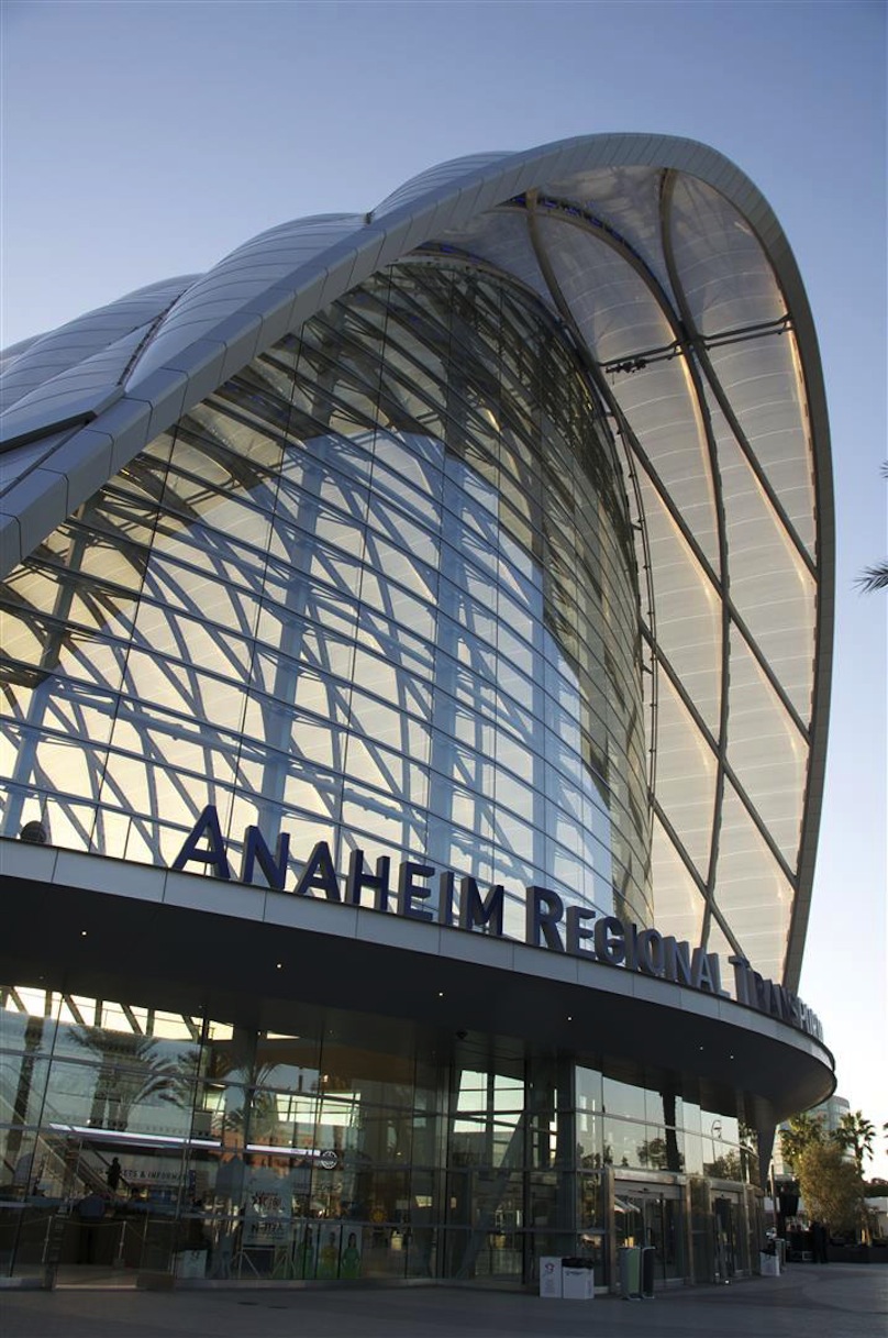 Image: Thornton Tomasetti Inc.
Building Team
Owner: City of Anaheim Public Works, Anaheim, Calif.
Owner: Orange County Transit Authority, Orange County, Calif.
Owner's Rep: STV, Inc., Los Angeles
Project Manager: Parsons Brinckerhoff, Orange, Calif.
Architect: HOK, Culver City, Calif.
*Structural Engineer: Thornton Tomasetti, Los Angeles (Submitting firm)
General Contractor: Clark Construction Group, Irvine, Calif.
Fabricator: Beck Steel, Inc., Lubbock, Texas (AISC Certified Fabricator)
Erector: Bragg Crane & Rigging Co., Long Beach, Calif. (AISC Advanced Certified Steel Erector)
Bender/Roller: Whitefab, Inc., Birmingham, Ala.
The Anaheim Regional Transportation Intermodal Center (ARTIC) in Anaheim, Calif., is as beautiful as it is functional. A hub for rail, bus, auto and bike travel, ARTIC is also ready for high-speed trains and street cars, the region’s next-generation transportation systems. The program includes a 68,000-sq.-ft terminal building beneath a soaring exposed steel structure. Rising from a height of approximately 80 ft at its southern end to 115 ft at the main entrance and public plaza, the ARTIC structure is approximately 250-ft long and 184-ft wide. The project included the Intermodal Terminal and the Metrolink/Amtrak concourse pedestrian bridge.
The intermodal terminal features a tapering vault of crisscrossing parallel arches – a lamella arch-shell hybrid. It spans 184 ft over a three-story, interior terminal building housing retail, ticketing, offices and other amenities. The special concentrically braced frames of the interior structure provide a stiffened base for the shell arches. The roof’s sculptural form is a high-tech take on the simple lines of old airship hangars and the light-filled grandeur of historic train stations. The thin shell’s curved geometry is optimized so that the amount of bending and deflection experienced under non-uniform environmental and seismic loads is minimized. The diagrid shell design has inherent structural redundancy and provides continuous load paths to transfer both gravity loads and lateral loads to the base.
The structural design for the roof employs long pieces of 14-in.-diameter, curved, interlocking steel pipes that form the complex yet efficient structure’s diagrid shell. Due to the inherent reliance of the shell’s performance on its form, the structural engineer collaborated closely with the architect to define its geometry, and a segment taken from a torus based on a catenary cross-section was selected as the most efficient shape to enclose ARTIC’s large interior volume.
After exploring multiple grids for the shell, Thornton Tomasetti achieved a solution that met structural requirements for performance and efficiency while also fulfilling the HOK’s aesthetic and spatial goals. The design was developed to define the arches as a series of compound curves, which made the steel easier to fabricate.
The steel shell is clearly visible through the façade, creating a variety of impressive visual effects, particularly when lit at night. The terminal is clad in translucent “Teflon-like” material known as ethylene tetrafluoroethylene (ETFE) – ARTIC is the largest single installation structure enclosed with ETFE in North America.
Because so much of ARTIC’s structure is exposed, aesthetic considerations were nearly as important as technical ones. The structural engineer and architect collaborated to design clean details that enhance, rather than detract from the building’s dramatic sculptural form.
The northern and southern end walls are glass structures that curve outward supported by tapering, built-up box section masts. These elements double as structural members, acting like bicycle-wheel spokes to stiffen the edge of the roof shell, which otherwise would deflect wildly at the significant end-discontinuities. The glazing system is highly transparent and hangs from the roof via steel cables, which are laterally supported by horizontal girts formed from rolled steel elements and steel armatures connected to the masts.
The north end-wall masts also support the cantilevering entrance canopy, which in-turn acts as a horizontal truss to laterally brace the masts. ARTIC’s unique design required constructability considerations from an early stage of the project. Thornton Tomasetti collaborated with the general contractor to develop a sequencing plan that required temporary shoring only at the first arches installed; the rest of the roof was self-supporting during erection.
Working with the steel fabricator, the structural engineer devised an adjustable backing plate for use in the complete joint penetration (CJP) welds that connect the intersecting steel pipes of the roof shell. The construction sequence made traditional internal ring plates impractical since they would get in the way of infilling arch pieces. An internal ring plate was designed that would telescope back into the pipe to allow placement of the infill sections. The design also included a screw and block to allow for the tolerances of the pipe fabrication while maintaining continuous contact between the plate and the interior pipe surface.
The terminal’s third level provides access to the new concourse bridge, a 262-ft-long covered pedestrian crossing that spans the existing tracks and provides elevator and stair access to the new rail platforms. The steel-framed bridge is supported by elevator shafts at its southern end – utilizing buckling restrained braces (BRBs) to resist lateral forces. At the northern end, groups of raking steel pipe columns with nested BRBs provide vertical and lateral support.
Due to liquefiable soils the terminal is constructed on a mat foundation following ground improvement works using deep dynamic compaction, while the bridge is supported by 10-ft-diameter cast-in-place concrete caisson piles placed between the tracks.
Despite its visual simplicity, ARTIC was a complex and challenging project. The entire design team relied heavily on integrated BIM for design exploration, analysis, team communication, documentation and coordination during design and in the field. The integrated model will be used by the owner for ongoing operations and maintenance. BIM’s value to the project was recognized by the American Institute of Archtects’ Technology in Architectural Practice Knowledge Community (TAP), which awarded the project its “Stellar Architecture Using BIM” citation earlier this year.
The transit center is expected to achieve LEED Platinum certification by incorporating initiatives including solar energy and potable water consumption reduction, stormwater runoff, construction, operational waste, air emissions reduction, optimization of climate conditions and open space areas. Through its iconic design, ARTIC will transform travel and deliver memorable experiences while providing convenient access to all of Southern California’s renowned destinations.
Presidential Award of Excellence in Engineering
John Jay College of Criminal Justice, New York
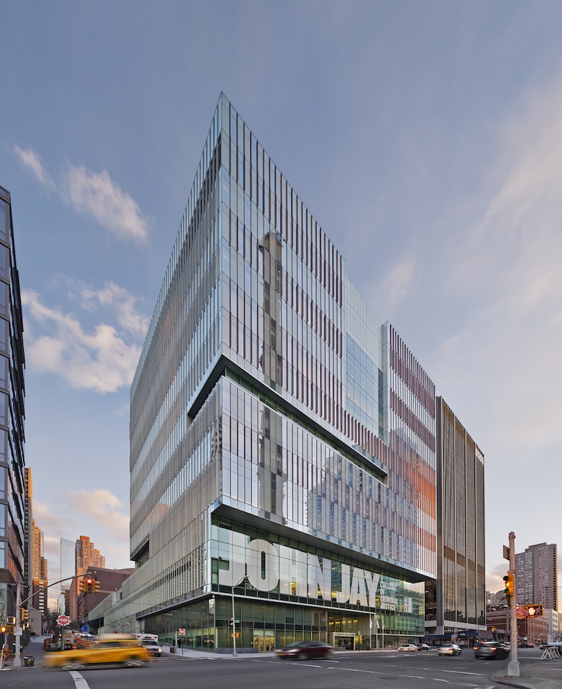 Image: Eduard Hueber Photography
Building Team
Owner: City University of New York
Owner: Dormitory Authority of the State of New York
Architect: Skidmore, Owings & Merrill LLP, New York
*Structural Engineer: Leslie E. Robertson Associates, New York (Submitting firm)
General Contractor: Turner Construction Co., New York
Fabricator: Owen Steel Co., Inc., Columbia, S.C. (AISC Certified Fabricator)
Detailer: Owen Steel Co., Inc., Columbia, S.C. (AISC Certified Fabricator)
Erector: Cornell and Co., Westville, N.J. (AISC Advanced Certfied Steel Erector)
Consultant: Langan Engineering & Environmental Sciences, New York
The City University of New York’s John Jay College of Criminal Justice expansion project is a new 625,000-sq.-ft, $400 million academic building in Midtown Manhattan. The facility consists of a 15-story tower on 11th Avenue and a four-story podium with a garden roof that connects to the college's existing Haaren Hall on 10th Avenue. Following significant growth in criminal justice interest over the last decade, the new building was planned to accomplish a doubling of the existing facilities and unification of the campus into one city block - creating an academic city within a city.
In response to a shallow Amtrak tunnel that cuts through a corner of the site, the John Jay structural system is distinguished by a grid of rooftop trusses which hang the perimeter of eight floors below. This creates a dramatic column-free cafeteria space on the fifth floor with views of the Hudson River for the full 195-ft width of the building.
Two layers of structure are provided to effectively isolate the building from the train vibration and noise. The main building structure cantilevers over and behind the train tunnel, which is enclosed with a hollow core precast plank ceiling and concrete crash walls. At points of convergence, creative detailing was required to maintain the load path and necessary separation.
Another challenge was accommodating the almost two-story change in grade between 10th and 11th Avenue. A second main entrance to the building occurs along 59th Street and negotiates this steep slope. To design for this condition, the perimeter columns – in an area that supported heavy loads from the rooftop garden – were eliminated, and the entrance was pulled back to allow room for the steps and ramps. Story-deep trusses were placed inside the walls of the fourth-floor classrooms to efficiently accomplish the 40-ft cantilever out to the tip of a V-shaped tapering canopy.
The interior architecture also responds to the sloped grade with a series of cascading staircases and escalators that complicated the structure, but allowed for fluid circulation to all parts of the campus. A large skylight supported by architecturally exposed narrow tube sections provides natural light into these main circulation areas and offers views in from the garden roof.
The 65,000-sq.-ft roof terrace serves as a new, outdoor gathering place for students and faculty. The planted green roof is landscaped with large grassy zones, full-sized trees, and decked outdoor dining areas.
Accommodating the necessary two layers of structure around the train tunnel mandated a practical limit to the weight that could be supported. After exploring numerous options, the hanging solution was favored by SOM and the Dormitory Authority of the State of New York, and adopted for numerous reasons, including assistance in achieving the series of distinguishing setbacks that frame the west façade’s main entrance along 11th Avenue. The hanging system was continued around the full perimeter to balance the weight, complete the column-free aesthetic, and take advantage of the thin plate hangers which could fit inside standard partition walls instead of traditional column enclosures. To maintain efficiency, the hanging system was stopped where the structure over the tunnel could accommodate conventionally framed floor weight. In coordination with the architect, the fifth floor was chosen for this transition, allowing the column-free floor to align with the podium roof garden. The primary construction challenge involved achieving approximately level floors opening day and a 2-in. stack joint in the curtain wall at the transition floor between the conventionally framed and hung structure. To simplify the steel frame erection, the design accounted for temporary columns at the fifth floor around the tower perimeter, and temporary angles bolted to the plate hangers above the sixth floor, to stiffen these elements during erection. This allowed the construction process to proceed similar to conventional construction and maintain the project schedule. Once the truss assembly was finished, jacks at the temporary columns slowly lowered the building and engaged the trusses. At this point the temporary columns and angles could be removed.
Calculating the required amount of vertical cambering of the steelwork (or how much to super-elevate the perimeter steel at each of the 26 hanger/column locations to account for the anticipated deflection during construction) was a challenge. Design estimates were based on the assumed construction schedule, estimated construction loads, and realistic modeling of the structural behavior. During construction, continuous surveying verified if the perimeter was behaving as we anticipated. Once a more accurate schedule and shop drawings were available for the nonstructural elements, a full reanalysis was performed incorporating what was being learned from the surveying. During this reanalysis it was determined that the perimeter would likely not come down as much as originally thought -- one reason being the curtain wall was 30% lighter than assumed -- and field adjustments were made to lower the steel frame prior to starting the truss erection. This adjustment proved effective as the final survey data received showed the building followed predictions closely and the final stack joint met the intended thickness.
While the building did not officially submit to the U.S. Green Building Council for certification, the project specifications were written to conform with many LEED certification requirements. The structural steel was sourced from mills regionally close to New York and produced from over 90% recycled content.
The John Jay College expansion project exceeded the expectations of owner and client -- giving the students and faculty a new state-of-the-art home they feel proud of along with the flexibility to adapt to future needs.
Related Stories

Mass Timber | Apr 25, 2024
Bjarke Ingels Group designs a mass timber cube structure for the University of Kansas
Bjarke Ingels Group (BIG) and executive architect BNIM have unveiled their design for a new mass timber cube structure called the Makers’ KUbe for the University of Kansas School of Architecture & Design. A six-story, 50,000-sf building for learning and collaboration, the light-filled KUbe will house studio and teaching space, 3D-printing and robotic labs, and a ground-level cafe, all organized around a central core.

75 Top Building Products | Apr 22, 2024
Enter today! BD+C's 75 Top Building Products for 2024
BD+C editors are now accepting submissions for the annual 75 Top Building Products awards. The winners will be featured in the November/December 2024 issue of Building Design+Construction.
Products and Materials | Mar 31, 2024
Top building products for March 2024
BD+C Editors break down March's top 15 building products, from multifamily-focused electronic locks to recyclable plastic panels.


BIM and Information Technology | Mar 11, 2024
BIM at LOD400: Why Level of Development 400 matters for design and virtual construction
As construction projects grow more complex, producing a building information model at Level of Development 400 (LOD400) can accelerate schedules, increase savings, and reduce risk, writes Stephen E. Blumenbaum, PE, SE, Walter P Moore's Director of Construction Engineering.

Building Tech | Feb 20, 2024
Construction method featuring LEGO-like bricks wins global innovation award
A new construction method featuring LEGO-like bricks made from a renewable composite material took first place for building innovations at the 2024 JEC Composites Innovation Awards in Paris, France.
Sponsored | BD+C University Course | Jan 17, 2024
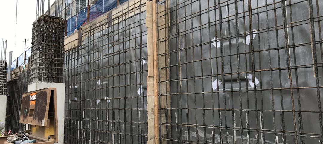
Waterproofing deep foundations for new construction
This continuing education course, by Walter P Moore's Amos Chan, P.E., BECxP, CxA+BE, covers design considerations for below-grade waterproofing for new construction, the types of below-grade systems available, and specific concerns associated with waterproofing deep foundations.

75 Top Building Products | Dec 13, 2023
75 top building products for 2023
From a bladeless rooftop wind energy system, to a troffer light fixture with built-in continuous visible light disinfection, innovation is plentiful in Building Design+Construction's annual 75 Top Products report.

Engineers | Oct 12, 2023
Building science: Considering steel sheet piles for semi-permanent or permanent subsurface water control for below-grade building spaces
For projects that do not include moisture-sensitive below-grade spaces, project teams sometimes rely on sheet piles alone for reduction of subsurface water. Experts from Simpson Gumpertz & Heger explore this sheet pile “water management wall” approach.

Mass Timber | Oct 10, 2023
New York City launches Mass Timber Studio to spur more wood construction
New York City Economic Development Corporation (NYCEDC) recently launched New York City Mass Timber Studio, “a technical assistance program to support active mass timber development projects in the early phases of project planning and design.”


