

![What went wrong? Diagnosing building envelope distress [AIA course]](/sites/default/files/Screen%20shot%202015-09-29%20at%209.46.33%20AM.png "What went wrong? Diagnosing building envelope distress [AIA course]")
With so many diverse components contributing to building envelope assemblies, it can be challenging to determine which of these myriad elements was the likely cause of a failure. Even seasoned building owners, managers, and facility professionals may find themselves faced with a confounding problem at the building exterior. These needn’t be catastrophic to be vexing, although sometimes, what began as a small, persistent issue can turn the corner suddenly to become a major fiasco.
LEARNING OBJECTIVES
After reading this article, you should be able to:
+ Apply lessons learned from examples of building envelope failures to the correct diagnosis and repair of deterioration, distress, and hazardous conditions at façades, roofs, plazas/terraces, and parking structures.
+ Evaluate signs of distress and failure to look beyond obvious conditions and uncover underlying sources of the problem, in order to develop remedial recommendations that resolve the problem for the long term.
+ Compare observed problems in similar construction types to contrast probable causes and identify the effects of different design flaws and construction errors.
+ Analyze catastrophic failure situations, including roof blow-off and façade detachment, to develop appropriate solutions and prevent the same type of problem from occurring in buildings of comparable construction and vintage.
TAKE THE EXAM
To earn 1.0 AIA HSW learning units, take the 10-question exam by clicking here.
Without proper diagnosis, building envelope problems are unlikely to go away. More often than not, superficial repairs actually make the situation worse, usually by trapping water or introducing materials incompatible with the existing construction. In the forensic examples that follow, we explore some of the varied causes of distress and failure in façades, plazas and building entrances, parking structures, and roofs, and look at the systematic, if sometimes complex, process of uncovering—and resolving—the source of the problem.
CASE STUDY #1: THE MASONRY Mystery
When our design professionals first visited the building pictured in Fig. 1, they found loose brick and mortar below the windows, failed sealant at jambs, aluminum sills bent upward at the front edge (Fig. 1a), and, most notably, significant gaps between the head of the window frame and the opening (Fig. 1b). Concerned that the windows may have fallen into their openings, the project team conducted a follow-up window investigation to find out what had gone wrong.
If the windows were indeed dropping into the wall, we would have expected to see loose, missing, or failed fasteners when we removed windows for testing. We saw none. Moreover, the window manufacturer confirmed that nothing was amiss with the attachment method or installation, both of which followed standard details.
What we found is that rather than the windows falling into the wall, the opposite was true: the wall was moving upward around the windows.
Building materials expand and contract at different rates. Brick expands over time; concrete shrinks. In this typical cavity wall construction, the brick masonry is only a one-brick-thick veneer. Behind it, an open cavity space allows for drainage, along with insulation and an air/vapor barrier. On the other side of this cavity is concrete masonry back-up, which provides the structure of the wall; unlike historic structures, which use solid brick masonry construction, newer buildings use brick only at the wall surface.
When combining multiple building materials in a single assembly, the design and construction must accommodate for their sometimes contradictory properties and behaviors. In response to moisture and humidity, brick expands slowly over time. The most common way to deal with this tendency is to place shelf or relieving angles at regular intervals along the height of the wall, with expansion joints beneath. By separating the brick masonry into regular segments and allowing those segments room to expand, these joints prevent cracking and failures.
Unfortunately, this building was designed without relieving angles or horizontal expansion joints. Although there are other ways to accommodate movement, these are limited to low-rise buildings, and no such provisions were made here. As a result, the cumulative expansion of all of the brick masonry over the entire four-story building led to substantial differential movement, particularly at the top floor, where the brick had expanded so much that the window sills were now sloped inward, toward the window, allowing water to collect along the frame (Fig. 1a).
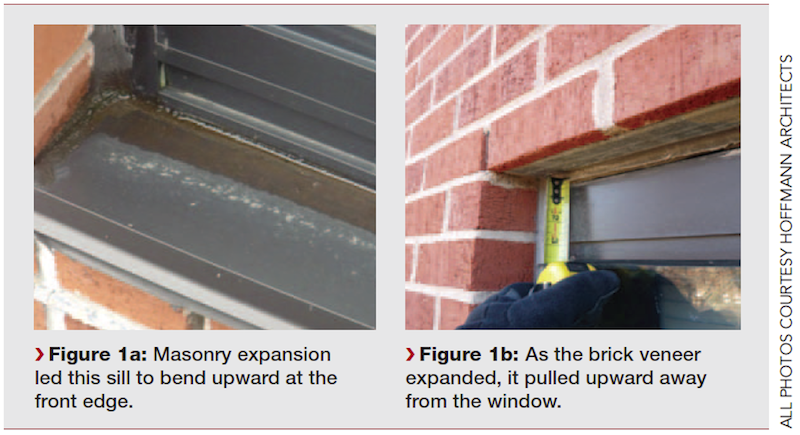
With the window units anchored to the concrete back-up (which shrinks over time as it dries out), and no provision for the expansion of the face brick, the window units remained in place while the brick veneer grew, making it appear at first glance that the windows were sinking. Only through a comprehensive masonry and window investigation could the real problem be uncovered.
In the next example (Fig. 2), relieving angles were present, but here we found displaced and spalled brick courses immediately above and below the relieving angle. Why?
A test probe into the distressed brick revealed asphaltic sheet flashing that was lapped but not sealed, which allowed water to travel between the overlapping layers. The flashing also had deteriorated and was no longer providing much protection. As water migrated through the porous brick and lingered in the deteriorating flashing, it led to corrosion of the steel relieving angle. As steel corrodes, it expands, placing outward pressure on the surrounding brick and leading to cracks and spalls.
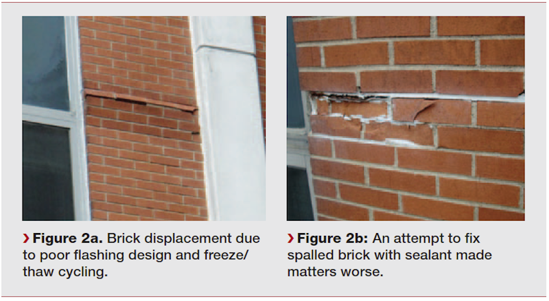
Someone with a caulk gun had sealed up the open joint at the relieving angle. Unfortunately, this joint was open for a reason: the porous mortar above the relieving angle was there to allow any moisture inside the wall to discharge. Once this escape route was covered over with impervious sealant, water collected inside the cavity wall.
As the outside temperature rose and fell, trapped water underwent successive freeze/thaw cycles. These changes in temperature and pressure forced off pieces of the outer surface of the brick, and led to the displacement visible in Fig. 2a, in which the face brick is nearly detached from the façade. As deterioration worsened, the maintenance staff reapplied sealant to the mortar joint in and around the spalled brick, inadvertently making the problem worse (Fig. 2b).
CASE STUDY #2: THE eerie enigma of the PLAZA/TERRACE
From the outside, the main entrance ramp and plaza (Fig. 3a) looked great: the plaza surface was clean and even, with no heaved pavers or uneven joints. Visitors to the building would have no idea of the horrors within: the spaces one and two levels below the ramp were so riddled with water damage that they became virtually unusable (Fig. 3b and 3c). What was going on?
The corroded steel beam in Fig. 3b sits directly under an expansion joint in the plaza, where the main entrance ramp meets a level surface; Fig. 3a shows this expansion joint from above, with the ramp extending upward to the left of the joint. Notice that the trench drain, at the right (red arrow), is downhill from the expansion joint (black arrow).
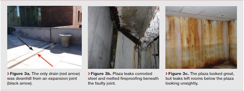
Every time it rains, water runs down the ramp toward the bottom, where it meets the open expansion joint and travels into the occupied space below. With the only drain situated downhill from the expansion joint, much of the water has already found its way into the building before it ever gets there.
The lesson: problems due to faulty waterproofing and drainage design don’t always show up on the surface. The pristine surface of this plaza belies the extensive deterioration below, where water infiltration has led to corrosion, disintegration of fireproofing materials, efflorescence, staining, and severe water damage to finished spaces. That’s why it’s so important to properly investigate the source of leaks, and to address the underlying problem.
CASE STUDY #3: THE perplexing puzzle of the PRECAST PARKING GARAGE
Precast, prestressed concrete double-tee construction has become one of the most common ways to build parking garages. Although factory fabrication of the precast members affords improved concrete quality control, the weak point for these garages tends to be the hundreds of steel connections that hold together the prefabricated units. Welded in the field, these connections tend to be the first point of failure, and when they fail, they tend to break not one by one, but catastrophically, in quick succession.
The garage pictured in Fig. 4 is a typical four-level freestanding parking structure constructed of precast concrete units in a double-tee (TT) configuration. The distinctive star-shaped pattern of corrosion and spalling in Fig. 4b occurred at regular intervals along many of the connections between precast members (Fig. 4a). With steel reinforcing present throughout the concrete deck, why was corrosion concentrated at these locations?
An investigation into the garage conditions, including test probes at areas of corrosion and spalling, provided some answers. As moisture penetrated through failed sealant joints at the double-tee connections, it encountered the embedded steel elements that connect one flange to the next. In addition to weld defects that ranged from poor configuration to faulty execution, the garage was constructed with mild carbon steel connections, rather than stainless steel. Despite a coat of anti-rust paint, the connections at this thinnest part of the concrete flange succumbed to corrosion, which extended outward from the welded plate, along the embedded structural steel.
Of greater concern, the fractured welds, combined with the missing concrete and loss of embedment area at the beam flanges, meant that the connection capacity at many of the intersections between precast units was significantly compromised. Although the distinctive reddish-brown rust stains and chipped concrete were obvious indicators of a maintenance problem, they don’t immediately reveal the serious nature of the damage from a structural standpoint.
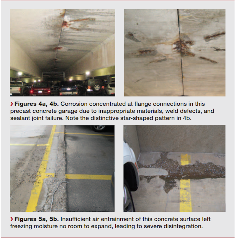
Previously, a misguided repair attempt applied patching material to the surface (Fig. 4b). Not only were these patches performed poorly, with insufficient surface preparation, they failed to address the source—and ramifications—of the failure.
Precast garages often have some cast-in-place elements, and the way in which these different types of concrete interact can impact the longevity of the garage, particularly at parking surfaces. In Fig. 5, portions of a tri-level precast garage became quite an eyesore—and a hazard to pedestrians—when crumbling concrete led to uneven surfaces. In some locations scaling was so severe that all that remained of the cast-in-place topping was loose aggregate and sand.
Even where the washes—humped concrete areas designed to promote drainage—had been replaced, signs of distress had already recurred, including spalls and cracks. During the condition assessment, we found that the concrete was unusually soft and porous, offering little resistance to chipping.
The freeze/thaw cycling typical of winters in the northern U.S. can pose problems for even the best designed and constructed parking garages, as these open structures are exposed to temperature fluctuations inside and out. As water absorbed by the concrete freezes and expands, it imparts great internal pressures. Repeated cycles of freezing and thawing can weaken the cement matrix and lead to deterioration. To mitigate this condition, concrete manufacturers incorporate microscopic air pockets through a process known as air entrainment, which allows water to expand as it freezes without damaging the concrete.
In this case, however, petrographic testing revealed that air entrainment of the cast-in-place concrete at curbs and washes was insufficient. As freezing moisture in the concrete expanded, it had nowhere to go, so it pressed outward, leading to cracks, spalls, and near total disintegration of the parking deck surface. Previous repair efforts temporarily improved concrete integrity, but even in these new areas, cracks had been left unaddressed, indicating that these locations, too, would likely deteriorate unless the poorly prepared concrete was completely replaced.
CASE STUDY #4: THE riddle of the RUNAWAY ROOF
In October 2012, during Hurricane Sandy, a catastrophic roof failure occurred at a suburban data center (Fig. 6). Situated on a ridge overlooking a river, the facility’s relatively open terrain left it exposed to the full force of the high storm winds. Although the roof structure and membrane assembly were designed to withstand even the intense wind pressures of a hurricane, the roof succumbed to the storm, the membrane lifting and the insulation becoming displaced below. We were charged with answering two questions: Was this failure due to insufficient design, faulty construction, or both? And how might the damage be repaired, with an eye to preventing similar incidents in future storms?
The first step was to perform calculations for the original assembly, to determine whether the design had been adequate to handle the intense wind load. Reviewing the original drawings, our design professionals determined that the structural roof deck was designed not only to meet the building code in effect at the time of construction, but to withstand loads that were even greater than those mandated by code.
The roofing assembly, composed of an ethylene propylene diene terpolymer (EPDM) membrane adhered to polyisocyanurate insulation board, also met accepted standards for wind uplift. Our research found that both the roofing assembly and the proprietary metal fascia at the roof edge exceeded even the most restrictive building code requirements set by the state. Beyond the mandates of the code, additional wind analysis based on wind speeds of up to 145 mph found that the roof design should have been sufficient to withstand the wind load.
The project team then looked to workmanship and detailing of the roof installation. Field investigation revealed several factors at play; one was that insulation boards could be easily lifted from the roof deck, and were not fully adhered. In some cases, asphalt adhesive coverage below the boards was a scant 25%. Many of the boards were “cupped,” or warped, which contributed to the poor adhesion. The temperature of the asphalt at the time of installation may also have been a factor.
At the roof edge, the EPDM membrane had been cut off at the top of the parapet, rather than extending over and down the outboard face of the blocking (Fig. 6b). In addition, wood blocking in the areas of failure was of insufficient depth to engage the fasteners. Compounding this lack of securement were voids beneath the edge metal where it extended over split-face concrete masonry units. These openings, along with the disengaged fasteners, allowed positive pressures to penetrate the underside of the edge metal.
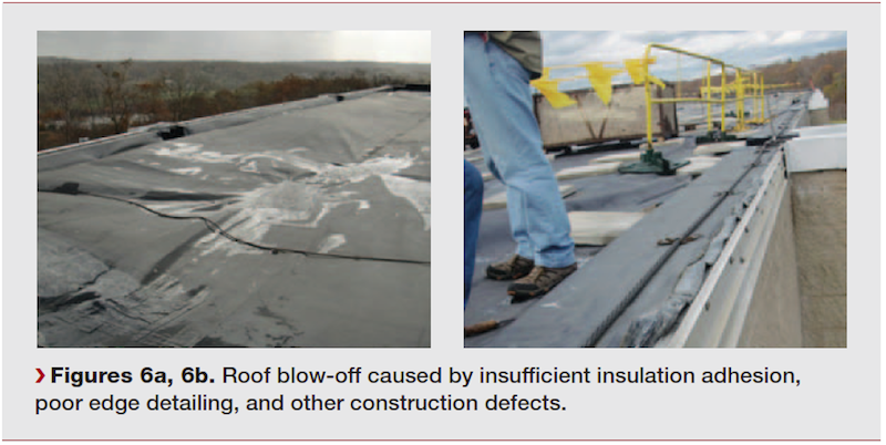
Large voids in the concrete roof deck and faulty cricket construction that allowed moist air to accumulate under the membrane also contributed to the roof blow-off. Although any one of these conditions might have caused the problem, the likely source was some combination of all of them. Despite the sound design of the structural deck and roofing assembly, a host of preventable errors during construction led to complete failure of the roof during the storm.
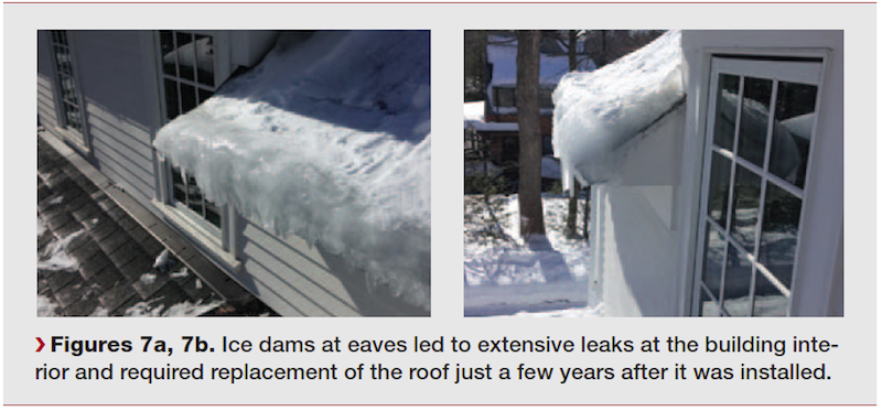
In a similar case, a residential building on a college campus experienced severe ice dams at the roof, leading to leaks at both above-grade levels and the basement ceiling (Fig. 7). During a very cold winter, some ice damming might be expected on older structures, but this was practically new construction. Clearly, more than just bad weather was to blame.
Our investigation uncovered several problems. Unbalanced ridge and soffit venting, combined with thermal penetrations in the attic insulation, allowed warm air to collect at the underside of the eaves, warming the roofing materials sufficiently to melt the snow. Once this snowmelt reached the gutter and drip edge, it re-froze (Fig. 7a). Over time, this repeated thawing and freezing created an accumulation of ice at the gutter, which allowed water to back up under the roofing shingles and penetrate to the building interior (Fig. 7b).
Based on notes made on the original drawings, we surmised that the ice and water barrier failed to meet code requirements, and was insufficient to the demands of the climate. Given its complexity, most of the roof should have been protected with an ice and water barrier beneath the roofing shingles; according to the drawings, only a small portion actually was safeguarded.
The original drawings also differed substantially from as-built conditions. By not accurately reflecting the existing roof framing or attic floor, the drawings did not provide sufficient guidance for the installers for ice and water barrier terminations, particularly where roof and wall areas intersect.
The lesson: coordinated drawings are critical to avoiding deficiencies in construction. Had the drawings adequately accounted for roof ventilation, attic insulation, ice and water barrier installation, and, critically, the intersections between various roof and wall areas, the ice damming could have been prevented. As it is, the college will need to disrupt accommodations at its residential facility and devote time and money to reconstructing a roof that is only a few years old.
CASE STUDY #5: tHE CURTAIN WALL conundrum
Winter weather was also the catalyst for building envelope failure at a very different type of building in a very different type of setting: a glazed curtain wall in the middle of Manhattan (Fig. 8). During a blizzard, a portion of the louver and frame system detached and fell from the building (Fig. 8a and 8b), landing on a roof setback (Fig. 8c), as well as on the roof of an adjacent building and the street below. Fortunately, no one was injured.
After reviewing existing documents and examining fallen and damaged material, our forensic team interviewed the curtain wall manufacturer to complete the picture of the probable cause of failure. The curtain wall system, constructed in 1962, employed a series of bolts and clips to secure the framing to the building structure. Newer curtain wall buildings use locking nuts to counteract vibration, but in buildings of this vintage, nuts and bolts working loose was not uncommon, even when some type of lock-washer was used. During the investigation, we found enlarged holes on some outrigger clip connections, which was consistent with fastener loosening.
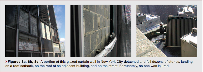
Other construction defects that likely contributed to the failure were the absence of an anneal slip, used to prevent galvanic action between dissimilar metals, between steel and aluminum outriggers, as well as failure to weld mullion splice sleeves. The expansion joint in the area of failure was only about a quarter inch wide, yet calculations and manufacturer data predicted an estimated three-quarters to one inch of expansion over the 20-foot aluminum mullion.
Although weather conditions at the time of failure were harsh, they shouldn’t have caused a failure of this magnitude. Instead, a combination of factors, ranging from design errors to construction omissions to limitations in the curtain wall securement system of the time, came together to pose a life-threatening situation. Something as small as a failure to properly account for the material properties of an assembly—in this case, expansion, galvanic action, and seismic forces—can lead to calamity.
The ONGOING SEARCH FOR SOLUTIONS
With so many components working together to create a weather-resistant, thermally insulating enclosure, compromising just one component can have a disastrous effect on the entire system. Where more than one flaw exists, the probability of failure is compounded.
For historic structures, including Modern-era buildings of the mid-twentieth century, time and exposure can aggravate flaws inherent to the original design or fabrication, increasing the risk of building envelope distress. Older buildings demand diligent maintenance and prompt, appropriate repairs to keep problems at bay.
But beware: newer buildings often fare no better than older structures. Even high-end construction can fall prey to oversights in design or craftsmanship that stem from lack of communication among trades, inexperience with emerging technologies and new building systems, or a failure to account for intersections between building elements.
Although the ideal situation would be to anticipate and prevent building envelope problems before they occur, building exterior distress is often inevitable. The next best thing to “build it right the first time” is “fix it right the first time.” With the correct diagnosis, you’re well on your way to a solution to your building system problem.
TAKE THE AIA COURSE EXAM NOW
Related Stories

Codes and Standards | Apr 8, 2024
Boston’s plans to hold back rising seawater stall amid real estate slowdown
Boston has placed significant aspects of its plan to protect the city from rising sea levels on the actions of private developers. Amid a post-Covid commercial development slump, though, efforts to build protective infrastructure have stalled.

Sustainability | Apr 8, 2024
3 sustainable design decisions to make early
In her experience as an architect, Megan Valentine AIA, LEED AP, NCARB, WELL AP, Fitwel, Director of Sustainability, KTGY has found three impactful sustainable design decisions: site selection, massing and orientation, and proper window-to-wall ratios.

Brick and Masonry | Apr 4, 2024
Best in brick buildings: 9 projects take top honors in the Brick in Architecture Awards
The Ace Hotel Toronto, designed by Shim-Sutcliffe Architects, and the TCU Music Center by Bora Architecture & Interiors are among nine "Best in Class" winners and 44 overall winners in the Brick Industry Association's 2023 Brick in Architecture Awards.

Retail Centers | Apr 4, 2024
Retail design trends: Consumers are looking for wellness in where they shop
Consumers are making lifestyle choices with wellness in mind, which ignites in them a feeling of purpose and a sense of motivation. That’s the conclusion that the architecture and design firm MG2 draws from a survey of 1,182 U.S. adult consumers the firm conducted last December about retail design and what consumers want in healthier shopping experiences.

Healthcare Facilities | Apr 3, 2024
Foster + Partners, CannonDesign unveil design for Mayo Clinic campus expansion
A redesign of the Mayo Clinic’s downtown campus in Rochester, Minn., centers around two new clinical high-rise buildings. The two nine-story structures will reach a height of 221 feet, with the potential to expand to 420 feet.
Sports and Recreational Facilities | Apr 2, 2024
How university rec centers are evolving to support wellbeing
In a LinkedIn Live, Recreation & Wellbeing’s Sadat Khan and Abby Diehl joined HOK architect Emily Ostertag to discuss the growing trend to design and program rec centers to support mental wellbeing and holistic health.
Architects | Apr 2, 2024
AE Works announces strategic acquisition of WTW Architects
AE Works, an award-winning building design and consulting firm is excited to announce that WTW Architects, a national leader in higher education design, has joined the firm.

Office Buildings | Apr 2, 2024
SOM designs pleated façade for Star River Headquarters for optimal daylighting and views
In Guangzhou, China, Skidmore, Owings & Merrill (SOM) has designed the recently completed Star River Headquarters to minimize embodied carbon, reduce energy consumption, and create a healthy work environment. The 48-story tower is located in the business district on Guangzhou’s Pazhou Island.

K-12 Schools | Apr 1, 2024
High school includes YMCA to share facilities and connect with the broader community
In Omaha, Neb., a public high school and a YMCA come together in one facility, connecting the school with the broader community. The 285,000-sf Westview High School, programmed and designed by the team of Perkins&Will and architect of record BCDM Architects, has its own athletic facilities but shares a pool, weight room, and more with the 30,000-sf YMCA.

Market Data | Apr 1, 2024
Nonresidential construction spending dips 1.0% in February, reaches $1.179 trillion
National nonresidential construction spending declined 1.0% in February, according to an Associated Builders and Contractors analysis of data published today by the U.S. Census Bureau. On a seasonally adjusted annualized basis, nonresidential spending totaled $1.179 trillion.


