

Vapor retarders play an important role in controlling water vapor flow and can be a major element in durable building enclosure design. (Note: Although there is some debate in the industry over terminology, “vapor barrier” and “vapor retarder” are used interchangeably here.) Experience shows that water vapor movement through building enclosure systems can result in problems in any climate—not just cold climates—where there is a difference in moisture levels between the interior and exterior.
LEARNING OBJECTIVES
After reading this article, you should be able to:
+ UNDERSTAND the basic physical forces that result in water vapor migration.
+ SELECT appropriate vapor retarder systems based on interior/exterior climate and general building enclosure construction parameters.
+ LIST the major factors that can impact water vapor migration through building enclosure systems.
+ DESCRIBE one or more ways to design durable, reliable, and effective building enclosure systems that appropriately manage water vapor.
Despite this understanding, there are still many misconceptions as to how and why water vapor flow occurs. This course will describe how to select and locate vapor retarders to control moisture migration and prevent condensation within the building enclosure.
It is important to distinguish between vapor flow and air leakage. Air leakage is three-dimensional in nature. It occurs through discontinuities within the building enclosure—holes, unsealed elements, etc.—or through air-permeable materials such as unsealed concrete masonry units. Moving air carries both heat and moisture, so air leakage creates the risk of condensation as well as heat losses and gains. That’s why air leakage has become such an important factor in the recent addition of air barrier requirements to most energy codes in the U.S.
Air barriers must be carefully detailed to provide continuity and may or may not also function as vapor retarders. Vapor flow is generally one-dimensional in nature, occurs via diffusion through solid materials, and is primarily governed by the permeability of materials to water vapor. Vapor retarders typically do not require the same level of continuity and detailing as air barriers to be effective.
Although vapor flow resulting from air leakage is many orders of magnitude greater than vapor flow through diffusion, this course will concentrate on vapor movement that occurs by water vapor diffusion, which is still an important element in building enclosure design even though it has taken a back seat to air leakage in recent years.
What Exactly Is "Vapor Flow"?
Water vapor travels from areas of high water content (also known as water vapor pressure, or the partial pressure of water vapor in a sample of air) to areas of low water content. Vapor pressure is a function of temperature and relative humidity (RH). The key concept in understanding RH is the “R”—for “relative.” RH, expressed as a percentage, can also be thought of as the percentage saturation for a sample of air at a given temperature.
RH alone cannot be used to determine the direction of water vapor flow because the saturation point is dependent on temperature: Warmer air has a higher storage capacity for water than cooler air. For that reason, it is possible for water vapor to flow from an area of low relative humidity (but high temperature) to an area of high relative humidity (at low temperature), as shown in Fig. 1.
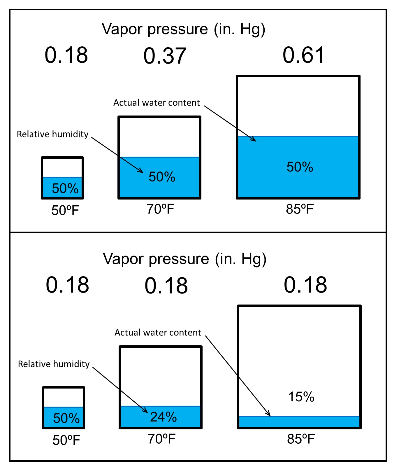 Fig. 1] The “relative” nature of relative humidity: Warm air can hold more water than cold air, so the “saturation point” of the air increases. Click image to enlarge.
For typical buildings, water vapor flows from the warmer side to the colder side of an enclosure system. This means that the direction of water vapor flow will vary by season and sometimes even on a daily basis, depending on the local climate. The ASHRAE psychrometric chart is a useful tool for determining the primary direction of water vapor flow under a given set of temperature and RH conditions. By locating a specific temperature and RH condition on the chart, you can read the absolute moisture content at those conditions. This is the humidity ratio, or HR, expressed in pounds of water per pound of dry air. As has been noted, water vapor will always flow from an area of higher absolute moisture content to an area of lower moisture content—in this case, from the higher HR to the lower HR on the chart.
While the direction of water vapor flow is determined by moisture levels on either side of an assembly, the magnitude of flow is determined by the vapor pressure differential across an element and the properties of the layers within that assembly.
- Water vapor permeability, measured in U.S. perm•in (1 perm•in = 1 grain/h•ft•inHg, where 1 grain = 1/7000 lb), is a material property that describes the rate of water vapor flow through a material for a given vapor pressure differential.
- Permeance, a layer property, describes water vapor flow through a specific thickness of material. It is measured in U.S. perms (1 perm = 1 grain/h•sf•inHg).
These measures are analogous to thermal conductivity and thermal conductance (R-value) when calculating heat flow.
Historically, vapor retarders have been considered to be materials with a water vapor permeance of 1.0 perms or less. Up through the mid-1900s, most buildings were constructed using solid, mass-masonry wall construction—brick, stone, and mortar—materials that were designed to absorb and store moisture. Since the basic wall materials were extremely durable and were not likely to be compromised by water vapor accumulation or condensation, vapor retarders were not used. Besides, vapor diffusion was not widely understood at the time.
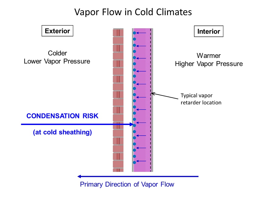 Fig. 2 ] Water vapor migration in cold climates is typically from the interior to the exterior. This leads to traditional code usage requiring a vapor retarder on the “warm-in-winter” side of an assembly. Click image to enlarge.
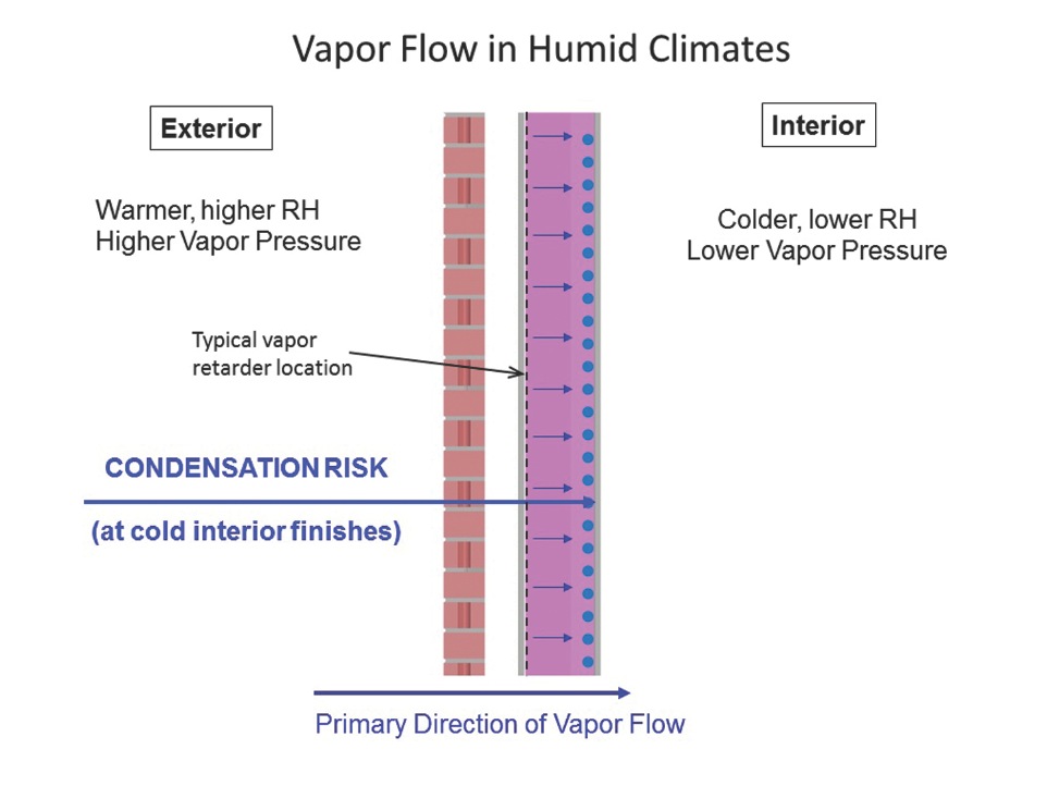 Fig. 3 ] Water vapor migration in hot/humid climates is typically the reverse of cold climates, with higher exterior moisture levels tending to “push” moisture into the building. Click image to enlarge.
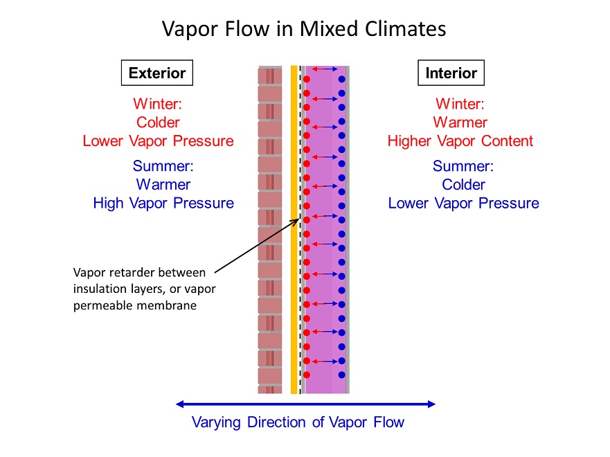 Fig. 4 ] Mixed climates do not have a dominant direction of water vapor migration. This creates the need to design for vapor flow in both directions, which may include split insulation and variable-permeance membranes. Click image to enlarge.
Vapor Flow In Today’s Construction
The same design principles regarding vapor retarders cannot be applied to today’s lightweight construction. Materials used in lightweight construction do not have the same moisture storage capacity as mass construction or the same durability in wet conditions. Light-gauge steel framing and gypsum- and wood-based sheathing are sensitive to moisture. The success of lightweight construction depends on keeping the moisture-sensitive components dry. Managing water vapor flow is one of several ways to accomplish that end.
As is well understood, condensation occurs when water vapor migrates to a cold surface and changes phase back to a liquid. Condensation requires a surface that is below the dew point—the temperature at which water vapor in air at a given temperature and RH will condense into a liquid—of the ambient interior environment.
In building enclosures, condensation is most often visible on glazing and framing systems, which are usually colder than the surrounding wall elements. Predicting condensation on directly exposed surfaces does not require a moisture migration analysis. Instead, a thermal analysis can be used to calculate surface temperatures, followed by a simple comparison to the interior design dew point.
Predicting and preventing concealed condensation due to water vapor flow can be much more difficult, for three reasons:
- Predicting condensation potential involves calculating both heat and moisture flows through an assembly. This is more complicated than calculating dew points and surface temperatures alone.
- Condensation-related damage to sheathing materials and wall framing can lead to premature degradation and the growth of mold, both of which are less likely to happen with exposed surfaces such as metal and glass on windows.
- Concealed condensation will typically not be noticed by building occupants until it has progressed to a level where staining, material failure, or odors have become apparent—at which point it is likely significant damage or mold growth has already occurred.
Preventing concealed condensation in walls, roofs, and other building enclosure components is the primary reason for using vapor retarders.
Designing For Vapor Flow
The most common question we get about water vapor flow is “Where do I put the vapor retarder?”—often followed by “Do I even need a vapor retarder?” Let’s look at the basic factors affecting vapor retarder design in buildings, as well as common mistakes that can lead to problems.
Until about 10 years ago, the most common way designers evaluated water vapor migration problems was through manual calculations using the ASHRAE dew point method. The chief disadvantage of manual calculations is that they focus on a single point in time. They do not account for the dynamic nature of changing weather conditions, or for heat and moisture storage and release in materials.
Computer simulations use the same basic formulas as manual methods, but perform thousands of calculations to account for the dynamic nature of water vapor flow and the impact of changing conditions, such as rainfall and solar heat gain.
In the following sections, rather than focusing on these specific analytical methods, we will present general guidance on designing to accommodate water vapor flow.
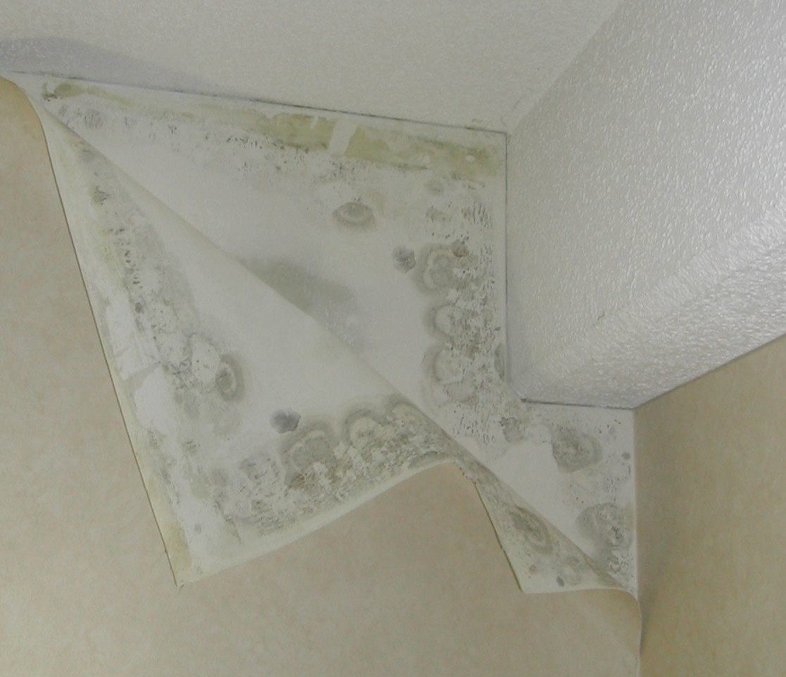 Photo shows mold growth behind vinyl wallpaper due to moisture migration in a structure in a hot and humid climate. Courtesy Simpson Gumpertz & Heger Inc. Click image to enlarge.
Evaluating Exterior Climate Factors
The location of a project is often the primary factor that dictates the need for a vapor retarder in the building enclosure, and how permeable the barrier needs to be. Historically, vapor retarders have been more common in northern climates due the condensation and moisture problems associated with winter conditions in those regions. That is why most codes initially required that vapor retarders be located on the “warm in winter” side of the assembly.
For typical interior environments in cold climates, water vapor flow is primarily from the interior to the exterior for most of the year. The intent of a vapor retarder on the interior of the insulation is to limit vapor flow to colder places in the wall, where it can condense (Fig. 2).
In warmer climates, the opposite is true, since the primary direction of vapor flow is from the exterior to the interior. Here, the issue is limiting water vapor migration from the exterior to the interior, where it can condense on the back of interior finishes—especially relatively impermeable layers like vinyl wallpaper (see photo above).
Mixed climates, such as the mid-Atlantic U.S., do not have a primary direction of water vapor migration. This makes it difficult to determine on which side of the assembly to place the vapor retarder. In these climates, vapor-permeable membranes or vapor retarders installed between layers of insulation are often the best options (Fig. 4). There are also vapor retarder materials, known as variable permeance vapor retarders, that change their permeance in response to changing RH conditions. These can be useful in mixed climates, as they can mitigate vapor migration in the cooler seasons but also allow drying during warmer, more humid, weather.
One element of the exterior environment that is often overlooked when designing vapor retarders is the moisture present in the local soil, which can flow into basements and slab-on-grade floors. Installing a vapor retarder below slab-on-grade construction greatly reduces vapor migration (but not necessarily liquid water flow) through the slab. Vapor migration through slabs can lead to problems with many types of flooring, from the reemulsification of water-based adhesives used for vinyl flooring, to warping of wood-based floor finishes.
For new construction, proper installation of vapor barriers below the slab is critical. Since there is almost always a higher moisture concentration in the soil than in the interior air (and, at this point in the project, the additional construction cost is relatively low), we almost always recommend using sub-slab vapor retarders regardless of the climate. Sub-slab vapor retarders should be installed directly below the concrete slab, as gravel or sand layers between the retarder and the concrete can allow water to build up below the slab, creating localized high moisture levels and driving vapor toward the building interior.
The potential for condensation depends on the magnitude of water vapor flow, which is dependent on the difference in water vapor pressure across a building element as well as the permeance of the materials in the assembly. For very cold or very humid climates, the great difference in vapor pressure between the interior and exterior means that vapor flows can be significant, and moisture problems potentially severe. This is why at least a Class (<0.1 perms) vapor retarder is necessary in places like Alaska or Florida, while buildings in mid-Atlantic (mixed) climates may only require a Class II (0.1 to 1.0 perms) vapor retarder, or no vapor retarder at all.
Interior Environment Considerations
Conditions within a building also have a significant impact on the requirements for vapor retarders. In mechanically ventilated, non-humidified buildings in northern climates, interior moisture levels are generally lowest when condensation potential is highest, due to the low levels of ambient moisture in the exterior environment. When humidification is added, even at low levels (35-40% RH), the vapor pressure differential between the interior and exterior can be double or even triple when compared to non-humidified conditions.
At even higher levels, such as those found in museums or indoor swimming pools, buildings with inadequate vapor retarders (or none at all) can experience significant damage from condensation within the enclosure, often in an alarmingly short period of time.
The use of wintertime humidification in a building is the biggest factor governing vapor flow magnitude in cold climates. It should be a red flag to the design team to be even more careful in the design of vapor retarders and building enclosure systems under such conditions.
A less well-understood problem is the reliance on operable windows for fresh air ventilation, which many building codes still allow. Buildings with continuous air barriers often experience high interior moisture levels during the colder months of the year, since occupants don’t want to have their windows open. This can result in high interior RH levels and consequent moisture problems in the enclosure. This situation highlights the need for coordination among architects, enclosure consultants, and mechanical engineers when designing the enclosure and identifying the typical interior conditions.
In mixed climates, humidified interior conditions will often mean that vapor retarders become necessary where they would otherwise not be needed.
In warm, humid climates, maintaining low interior moisture levels will increase the vapor pressure differential and the resulting vapor drive to the interior. This is often the case in office buildings, where occupants tend to undercool the space for better comfort. However, this should not be a problem in warm, humid climates, since a well-designed building will already have a strong exterior vapor retarder.
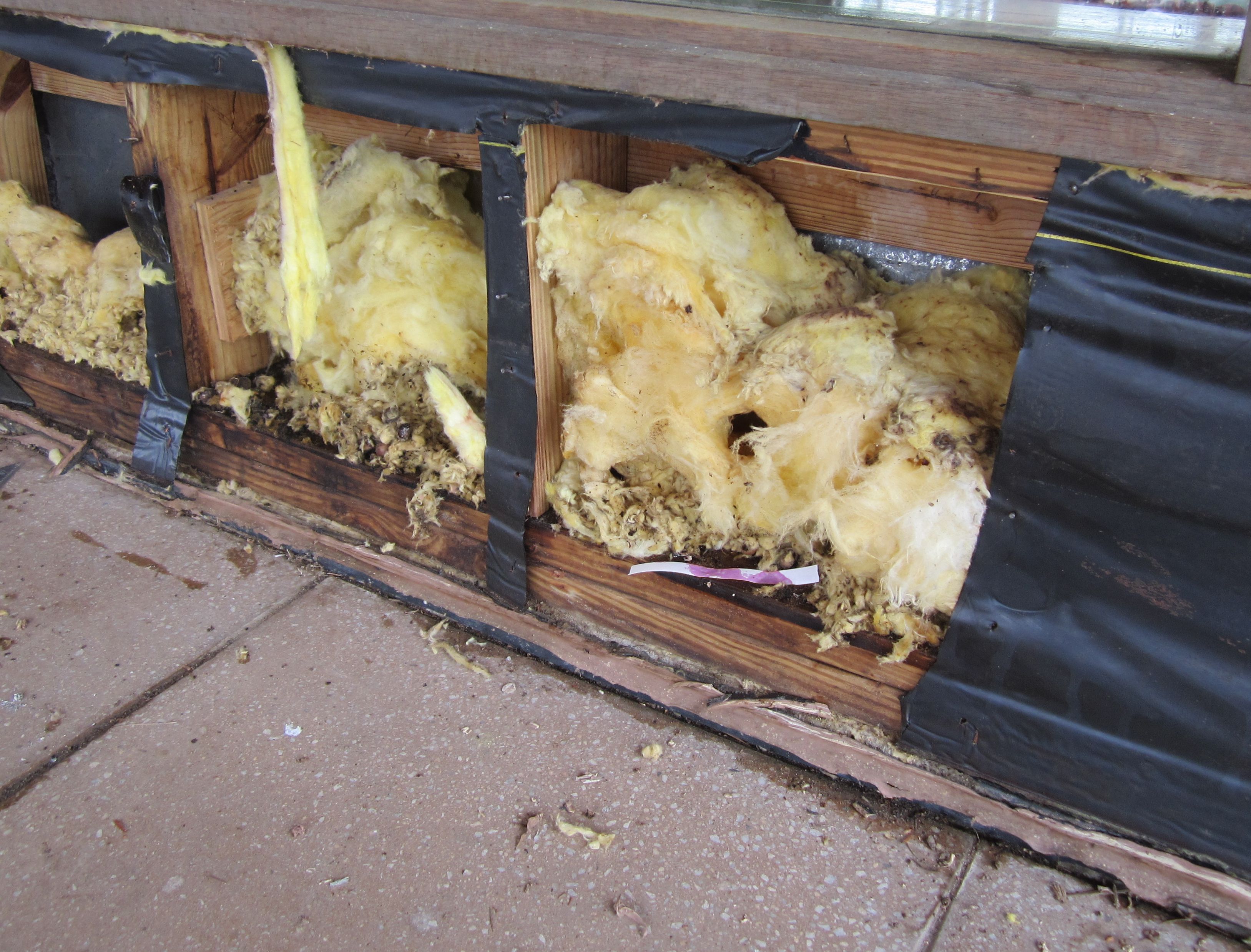 Pictured: Moisture-related damage to insulation and wall framing due to the vapor retarder having been installed—improperly—on the “cold” side of wall insulation. Courtesy Simpson Gumpertz & Heger Inc. Click image to enlarge.
Enclosure Construction Factors
Once the interior and exterior conditions have been determined, designers must evaluate the overall makeup of a wall or roof as part of designing for water vapor migration. Many factors need to be taken into account, notably:
Durability of materials. Concrete block and solid brick masonry are less susceptible to damage than materials like gypsum wallboard and oriented strand board sheathing. Vapor retarders may not be necessary in this type of construction. In older buildings, such as those constructed with solid brick, adding a vapor retarder may end up causing problems by limiting drying of the wall and increasing the risk of freeze-thaw damage to the masonry.
Reverse vapor drive. In wall systems with highly absorptive exterior cladding, such as split-face concrete masonry units or porous brick masonry, solar gain on the wet cladding can lead to a localized water vapor flow toward the interior of the building, even under relatively cool exterior conditions. As solar heating forces the wall to dry out toward the interior, a vapor retarder—even one installed per code on the interior side of the wall insulation—can trap that moisture within the assembly. A more permeable vapor retarder likely would allow the system to dry out more quickly and prevent moisture accumulation.
This highlights the risk of using vapor retarders in solid masonry walls that lack dedicated exterior weather barriers. Reducing the drying ability of the wall can lead to high moisture levels in the masonry, which can raise concerns about durability and moisture buildup within interior finishes.
EDITOR’S NOTE
Brief additional reading is required for this course.
To earn 1.0 AIA CES HSW learning units, study
the article carefully and take the exam.
Unexpected vapor retarders. Many building enclosure materials or finishes can act as vapor retarders, even without being labeled as such. The most common example is vinyl wallpaper, which can have a permeance of 0.5 perms or less for some products. Metal back pans in curtain wall construction and foil backing on some gypsum wallboard products also can act as “stopping points” for moisture that result in concealed condensation. They should be evaluated as part of the overall water vapor flow plan.
Weather-resistive barriers often have very low permeance (≤0.05 perms), making their use in some wall assemblies and climates problematic. This is often the case in colder climates, where designers and installers routinely select self-adhered rubberized asphalt membranes for use on exterior sheathing based on the superior waterproofing performance of these products, without considering their impact on vapor flow when installed on the sheathing outboard of the primary wall insulation—the wrong side for this climate. Some exterior insulation is almost always required to prevent condensation when impermeable weather barriers are used in cold climates.
Vapor traps. Theoretically, putting a vapor retarder on both sides of the wall or roof insulation would address vapor flow in both directions, but doing so would eliminate the potential of the wall to dry out in the event of a leak or excessive built-in moisture. That’s why it’s good practice to avoid using multiple vapor retarders in an assembly, and, depending on the season, to allow the wall to dry to both sides of the vapor retarder.
In some cases, a variable permeance vapor retarder applied on the interior can be useful if there is already an exterior vapor retarder, as it can limit moisture migration to the exterior during cold weather but allow for some drying to the interior during warmer weather.
One case where vapor traps are unavoidable is in low-slope, compact (unvented) roof systems. In this case, especially in cold climates, a vapor retarder is needed to limit vapor flow into the roof assembly, which will typically have a relatively impermeable roof membrane on the outboard side. This makes the assemblies inherently susceptible to moisture accumulation in the event of leakage. However, leakage in a roof is unlikely to go unnoticed, so the potential for significant accumulation without detection is fairly low for most roofs.
Which side is the warm side? Back when typical exterior walls only had insulation between the studs, the “warm” side was easy to locate. Most modern energy codes now require continuous insulation outboard of framed wall assemblies, which usually places the weather-resistive barrier on the sheathing between layers of insulation (Fig. 4). Computer analysis of moisture migration is often necessary to analyze these cases and determine the appropriate levels of insulation, as well as the appropriate vapor permeance for the vapor retarder within the wall.
Water vapor transmission is an important design consideration that can determine the success or failure of the building enclosure. Building codes provide some guidance, but they don’t cover the wide range of factors that can affect enclosure performance. The local climate, the interior environment, and the nature and configuration of the other materials in the enclosure must all be taken into account to produce a system that functions not only under the design conditions but also has sufficient redundancy to tolerate extreme events such as water leakage or intermittent spikes in interior or exterior conditions.
Designing the enclosure to address water vapor migration requires an understanding of the general factors that impact vapor flow and applying those factors to the specific conditions on a project. Where the guidelines described in this course are not sufficient, computerized analysis may be necessary to address water vapor migration.
A Brief History of Vapor Retarders and Building Codes
The first studies of vapor diffusion through building enclosures were conducted in the late 1920s by Frank Rowley, PhD, Professor of Mechanical Engineering at the University of Minnesota, according to William B. Rose, writing in APT Bulletin (“Moisture Control in the Modern Building Envelope: The History of the Vapor Barrier in the U.S., 1923-1952,” 1997).
Up to that point, the primary means of preventing condensation and mold growth in high-humidity buildings—typically factory and mill buildings where wet interior operations led to high interior relative humidity levels—was to use a lot of thermal insulation and raise the interior surface temperature. Rowley first recommended the use of vapor retarders after conducting an experiment in which the wood sheathing in the test assembly he constructed collected more moisture without a vapor retarder than with one.
Historically, building codes have not always specified the inclusion of vapor retarders. Vapor retarders were only specified for crawl spaces in the 1968 New York City Building Code. In the first edition of the Massachusetts Building Code (1974), the only requirement for vapor retarder use was that it not increase the fire hazard characteristics of the building. Vapor retarders first became a requirement in Massachusetts in 1980, where a maximum 1.0 perm vapor retarder was required on the winter warm side of walls, ceilings, and floors enclosing conditioned space. In 2001, Massachusetts increased this requirement to 0.1 perms, before eventually going back to the more typical 1.0 perm requirement in later editions.
Vapor retarders were incorporated into the Canadian Building Code as early as 1970. Class I or II vapor retarders were required in above-grade walls, depending on resistance needed to control vapor movement. The National Building Code of Canada requires that vapor retarders for residential buildings have a vapor permeance of <1 perm, but only requires that vapor diffusion be controlled if an assembly “would be adversely affected by condensation.”
Most current building codes define three classes of vapor retarders: I, II, and III. The rating is based on the manufacturer’s certified testing or a tested assembly, typically per ASTM E96 – Standard Test Methods for Water Vapor Transmission of Materials. Class I vapor retarders are less than 0.1 perms. Class II vapor retarders are between 0.1 and 1 perms. Class III vapor retarders are between 1 and 10 perms.
Most metal and plastic films qualify as Class I. Kraft paper facing on insulation and some foam plastic insulations are generally Class II. Latex paint over gypsum wallboard, some types of building paper, and some wood sheathings are generally Class III.
The term “vapor barrier” is often used interchangeably with “vapor retarder.” While many practitioners consider a vapor barrier—which effectively stops almost all water vapor flow rather than just retarding or slowing it—to be a Class I (or less permeable) vapor retarder, there is still no consensus in the industry on which is the proper term to use. The most common use of the term vapor barrier is for materials installed below slabs-on-grade, which are intended to eliminate vapor flow from the ground, as opposed to wall materials that can tolerate some water vapor flow, or where such flow is desired for redundancy (to allow drying).
In the 2015 International Building Code, Class I and II vapor retarders are to be provided in climate zones 5, 6, 7, and 8 and marine 4 on the interior side of above-grade framed walls. One of the exceptions is in construction—primarily mass masonry construction—where moisture or frozen condensate would not damage the materials. Class III vapor retarders are only permitted where the assembly demonstrates a sufficient ability for moisture to escape, such as vented assemblies and certain insulated sheathing assemblies as defined in the code.
About the Authors: Sean O’Brien is a Principal at the engineering firm Simpson Gumpertz & Heger and head of SGH’s Building Technology Division in New York City. Matthew Vong is an Engineer in the same division, based in New York. Both specialize in building science and building enclosure performance.
Related Stories

Sponsored | | Sep 8, 2014
Metal roof and wall panels provide strong wind resistance
In areas that experience strong winds, metal roof and wall panels provide a sturdy, well-tested option for building envelope design.

| Sep 7, 2014
Building the cladding palette: panels, rainscreens, and veneers [AIA course]
When it comes to cost, performance, and aesthetics—not to mention maintenance and long-term resilience—the evaluation of cladding materials and façade systems is more complex than ever. This course is worth 1.0 AIA CES HSW learning units.

Sponsored | | Aug 16, 2014
Fire-rated framing system makes the grade at Johnson & Wales University Center
The precision engineering of TGP’s Fireframes Aluminum Series creates narrow profiles and crisp sightlines at Johnson & Wales University Center for Physician Assistant Studies
| Jul 17, 2014
A harmful trade-off many U.S. green buildings make
The Urban Green Council addresses a concern that many "green" buildings in the U.S. have: poor insulation.

| Jul 1, 2014
Sochi's 'kinetic façade' may steal the show at the Winter Olympics
The temporary pavilion for Russian telecom operator MegaFon will be wrapped with a massive digital "pin screen" that will morph into the shape of any face.

Sponsored | | Jun 4, 2014
Fiber cement panels bridge historic and modern at Minneapolis apartment complex
The design team for the Third North apartment complex specified Nichiha’s Illumination Series architectural panels in a blend of six colors—divided into swaths of reds and swaths of grays—that combine with a rectilinear shape to complement nearby brick.
| May 27, 2014
Fire Rated Glass contributes to open lab environment at JSNN
Openness and transparency were high priorities in the design of the Joint School of Nanoscience & Nanoengineering within the Gateway University Research Park in Greensboro, N.C. Because the facility’s nanobioelectronics clean room houses potentially explosive materials, it needed to be able to contain flames, heat, and smoke in the event of a fire. SPONSORED CONTENT
| May 27, 2014
Contractors survey reveals improving construction market
The construction industry is on the road to recovery, according to a new survey by Metal Construction News. Most metrics improved from the previous year’s survey, including a 19.4% increase in the average annual gross contracting sales volume. SPONSORED CONTENT

| May 20, 2014
Kinetic Architecture: New book explores innovations in active façades
The book, co-authored by Arup's Russell Fortmeyer, illustrates the various ways architects, consultants, and engineers approach energy and comfort by manipulating air, water, and light through the layers of passive and active building envelope systems.
| May 20, 2014
Using fire-rated glass in exterior applications
Fire-rated glazing and framing assemblies are just as beneficial on building exteriors as they are on the inside. But knowing how to select the correct fire-rated glass for exterior applications can be confusing. SPONSORED CONTENT


